Digitally Adjustable High-Voltage Power Supply for Nixie Tubes
Table of Contents
Set the output voltage via I²C, no conventional potentiometer needed!
This revolutionary capability and other useful features greatly simplify building a Nixie Tube Project!
Overview
This module supplies all the important voltages needed for a Nixie Tube Clock or any other project that needs voltages up to 175V at a few milliamps.
In addition to the high voltage, it also has two other, low voltage rails: 3.3V and 5V! These can power the microcontroller, sensors, LEDs etc.
The module is powered by a single 12V DC supply.
What's really unique about my design is the ability to precisely set the output voltage for the Nixie Tubes I²C. This enables a whole range of possibilities, since the voltage is not always constant and doesn't need to be set with a potentiometer manually.
Here's an overview of all features:
- 12 V DC input
- Outputs:
- 85 V to 170 V @ 15 mA max
- 5 V @ 1.25 A max
- 3.3 V @ 300 mA max
- Advanced control capabilities:
- Shutdown of high-voltage generation
- Precise setting of high-voltage output via I²C
- MAX1771 control IC
This module is easy to use and can be controlled by any microcontroller with I²C. Examples on how to use it are provided for the Arduino environment.
Features
I made this module since I needed a HV PSU for a smaller 4-tube Nixie Clock. Since the space on the main PCB was limited, I decided to make a standalone power supply that could later be fitted into the base of the clock.
Here's a comprehensive list of all the features.
High voltage and common low voltage outputs
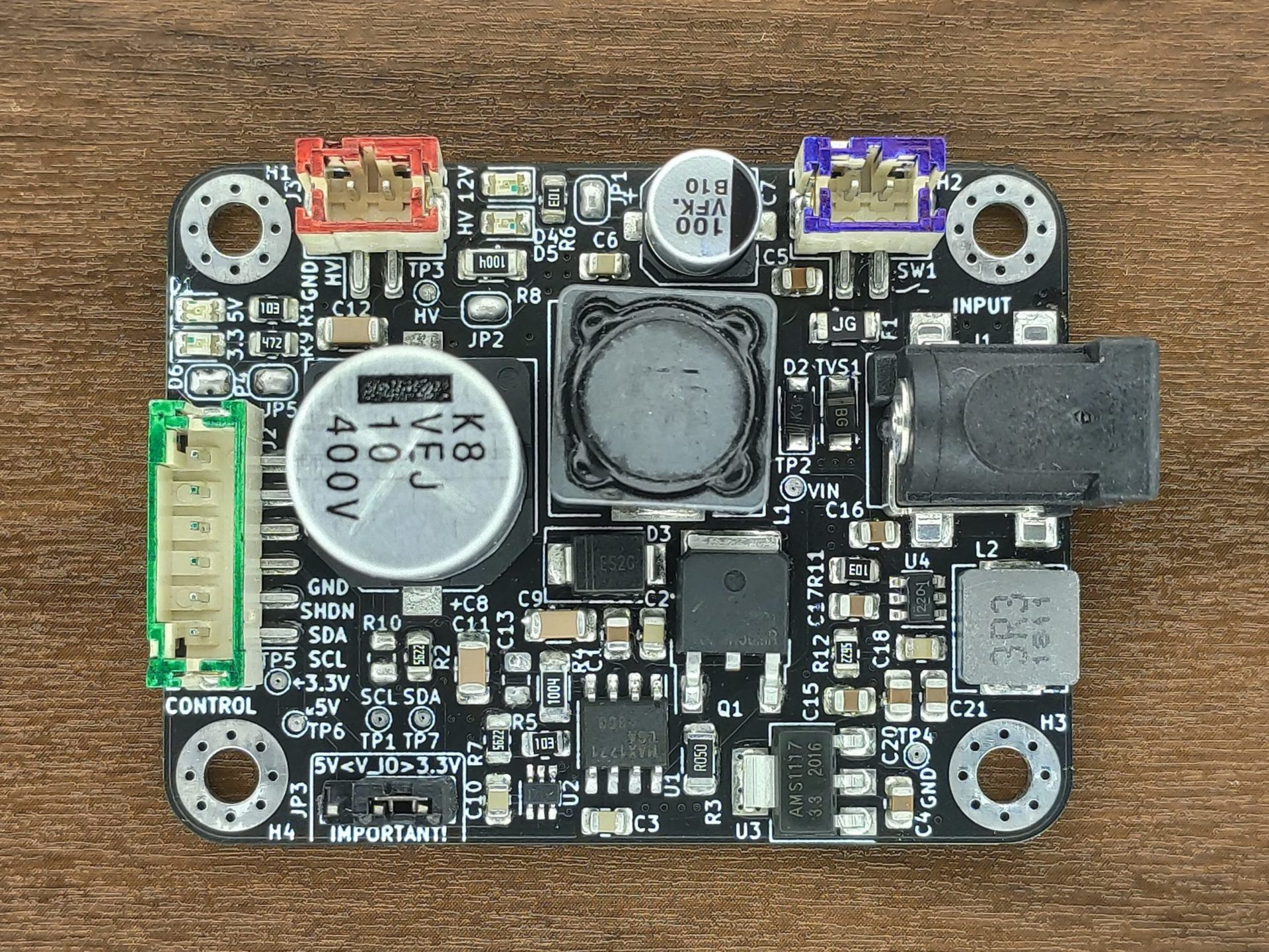
The module outputs an adjustable high voltage and in addition to that 5V and 3.3V. Both of which can be used to power a microcontroller and peripherals.
- 85 V to 170 V @ 15 mA max
- 5 V @ 1.25 A max
- 3.3 V @ 300 mA max
All outputs are derived from one 12 V input.
Easily adjustable output voltage
Adjusting the output voltage is easy and can be done quickly! Much faster than the video shows actually. In total, 128 individual steps are possible.
Simple integration
With its connectors and small size, the module can be integrated into basically any project!
Pinout diagram
This handy file will help you to quickly grasp all important details!
Hardware
Mechanical specs
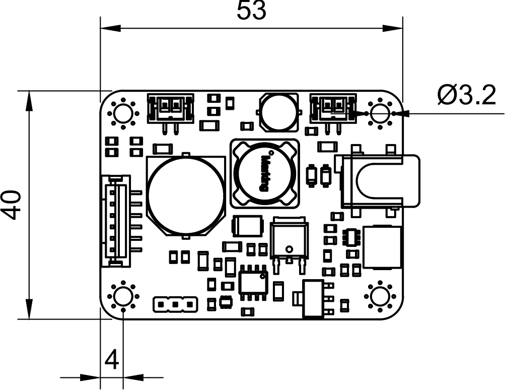
The size of the PCB is 53mm by 40mm.
There is an M3 mounting hole on each corner, 4mm from the side.
2mm-pitch connectors are used for the On-Off switch, the high-voltage output and the control / low-voltage supply rails.
See the provided PDF file for exact dimensions for all relevant parts.
Software
Overview
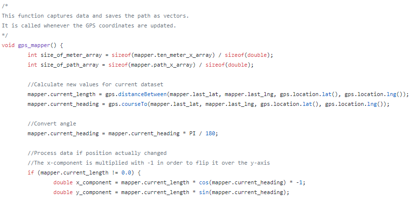
The provided code snippets are written for the Arduino IDE.
Due to the simplicity it shouldn't be an issue to port it to other platforms.
The code is available on the projects GitHub page.
Test & Verification
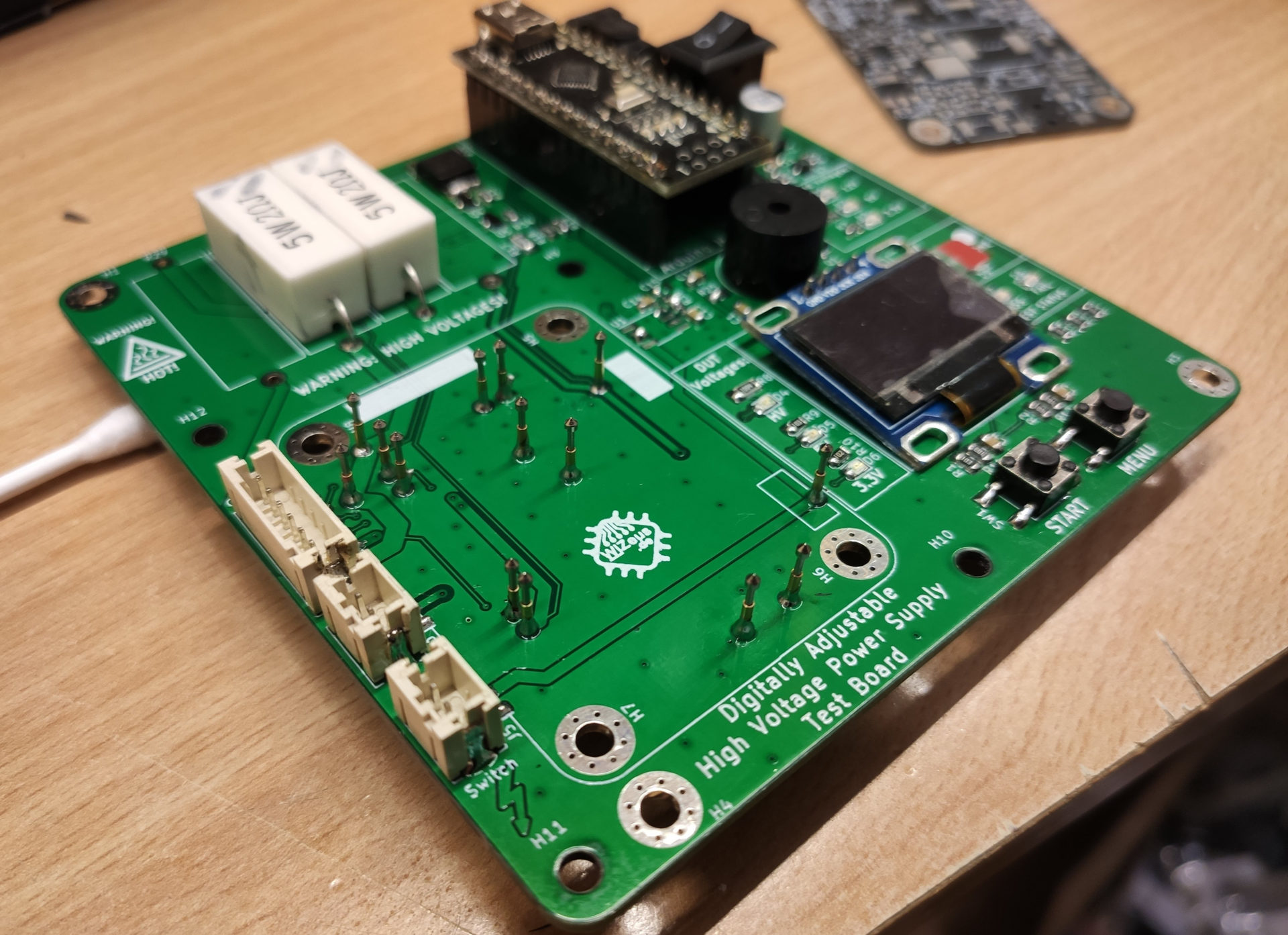
Each assembled module can easily and quickly be tested with the custom-made test-jig. It uses spring loaded pins that make contact with test-points on the bottom side of the PCB.
These test points are only present on the latest revision of the PCB. Some of the images on this site show earlier revisions.
An automated test-program runs several tests and outputs the results via the screen / LEDs.
Photos
Here are some additional images of the project.
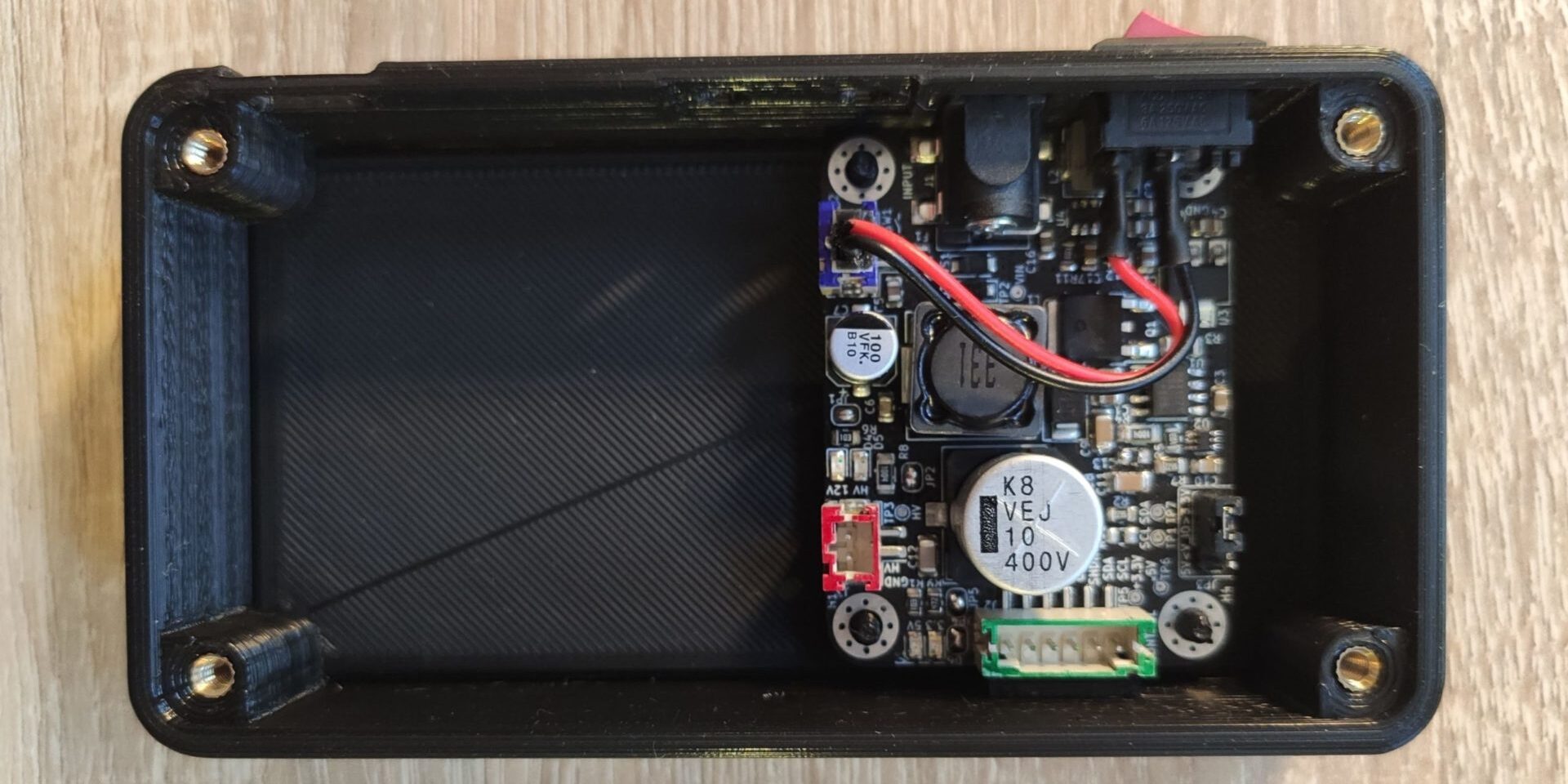
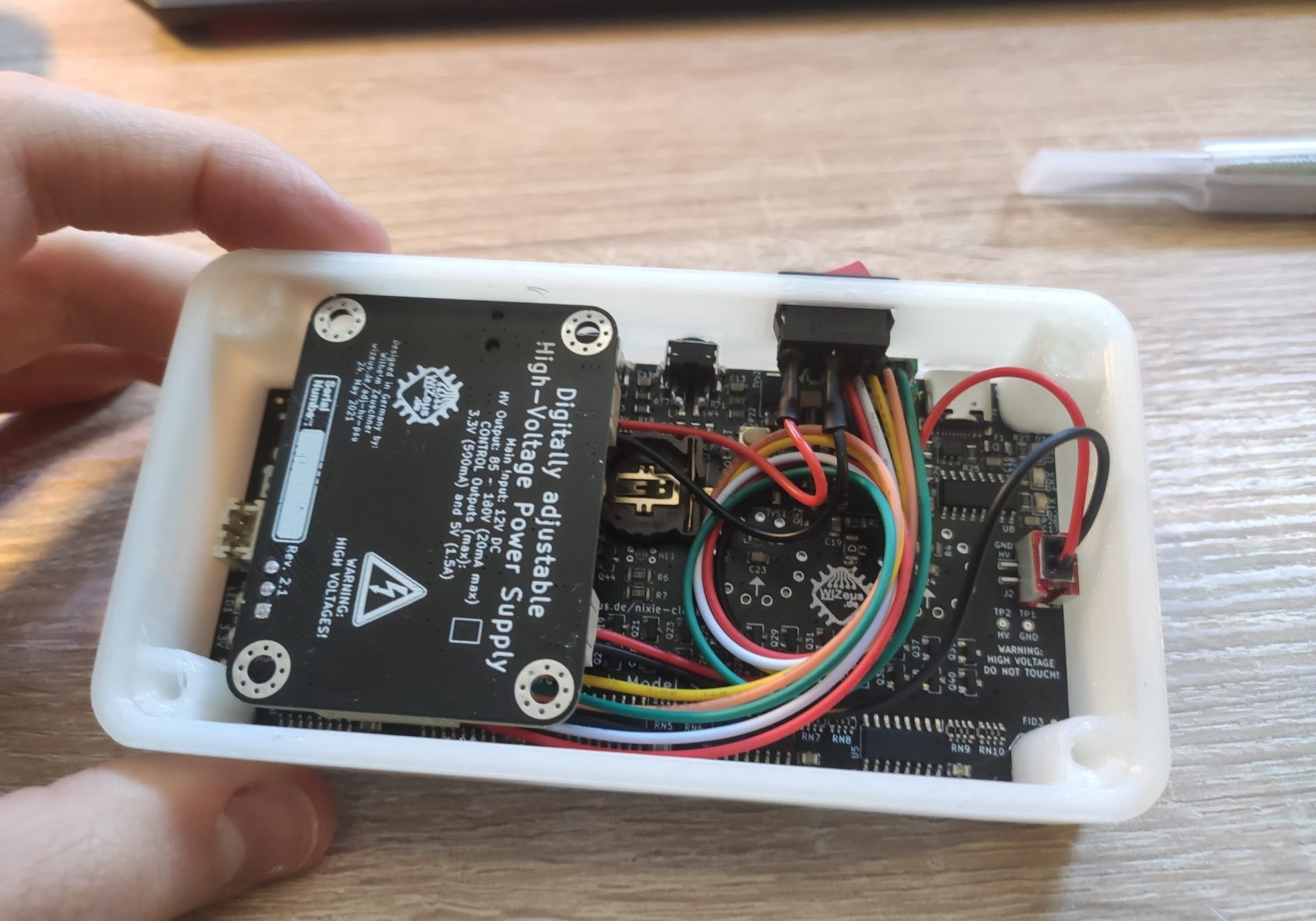
The module is mounted in the first prototype 3D-printed case.
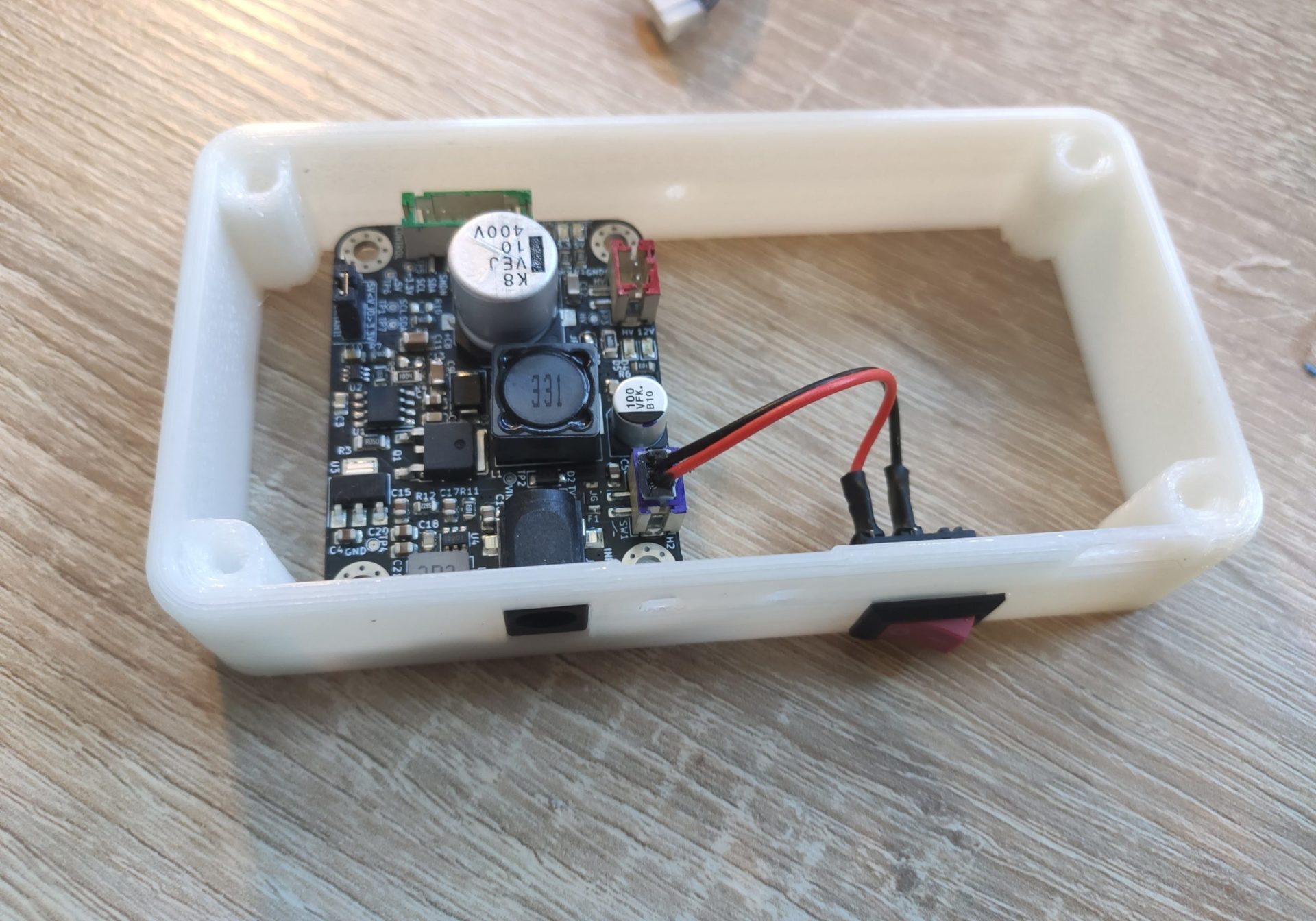
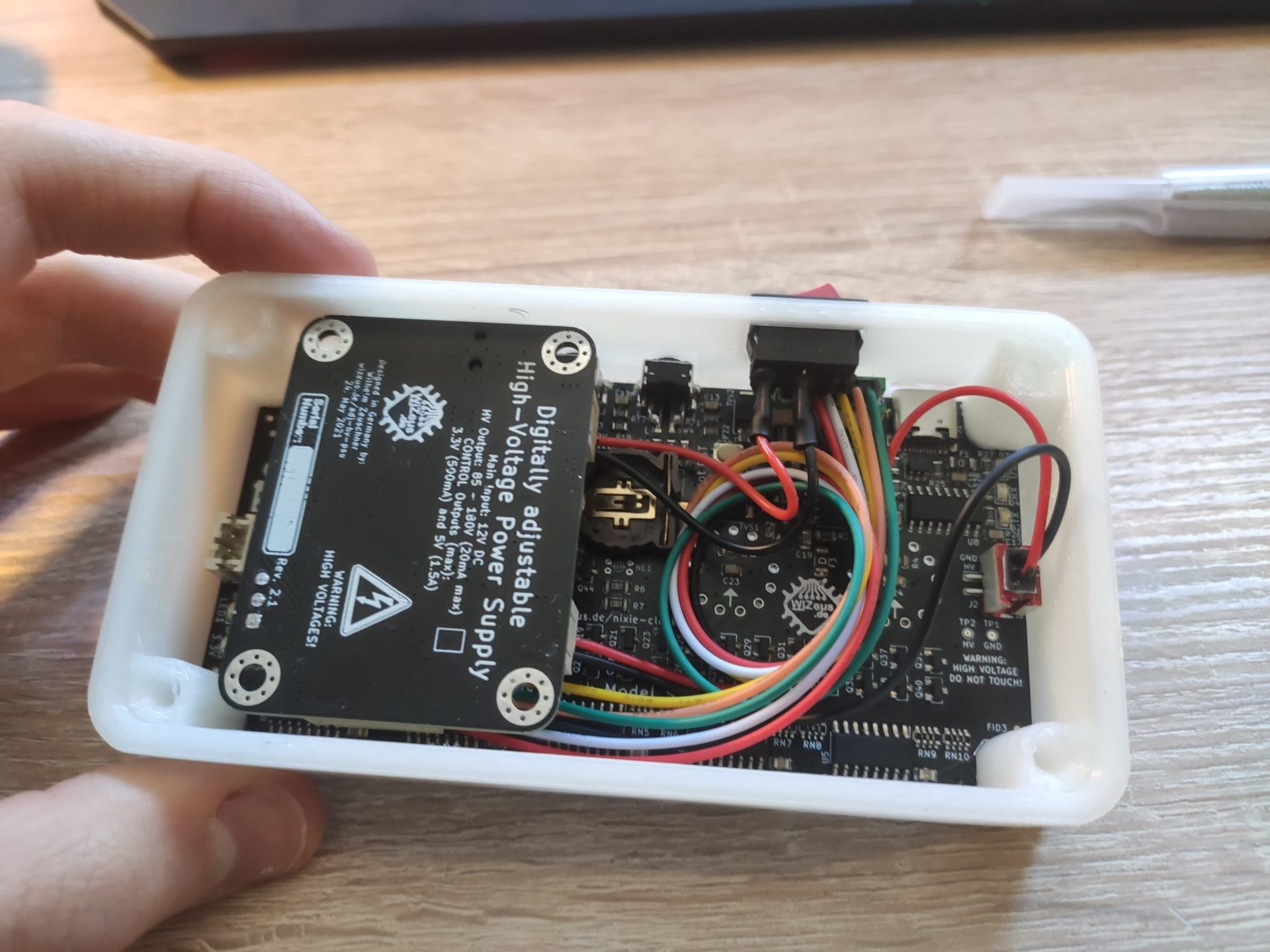
Here the main Nixie Clock PCB was added and the wires have all been connected.
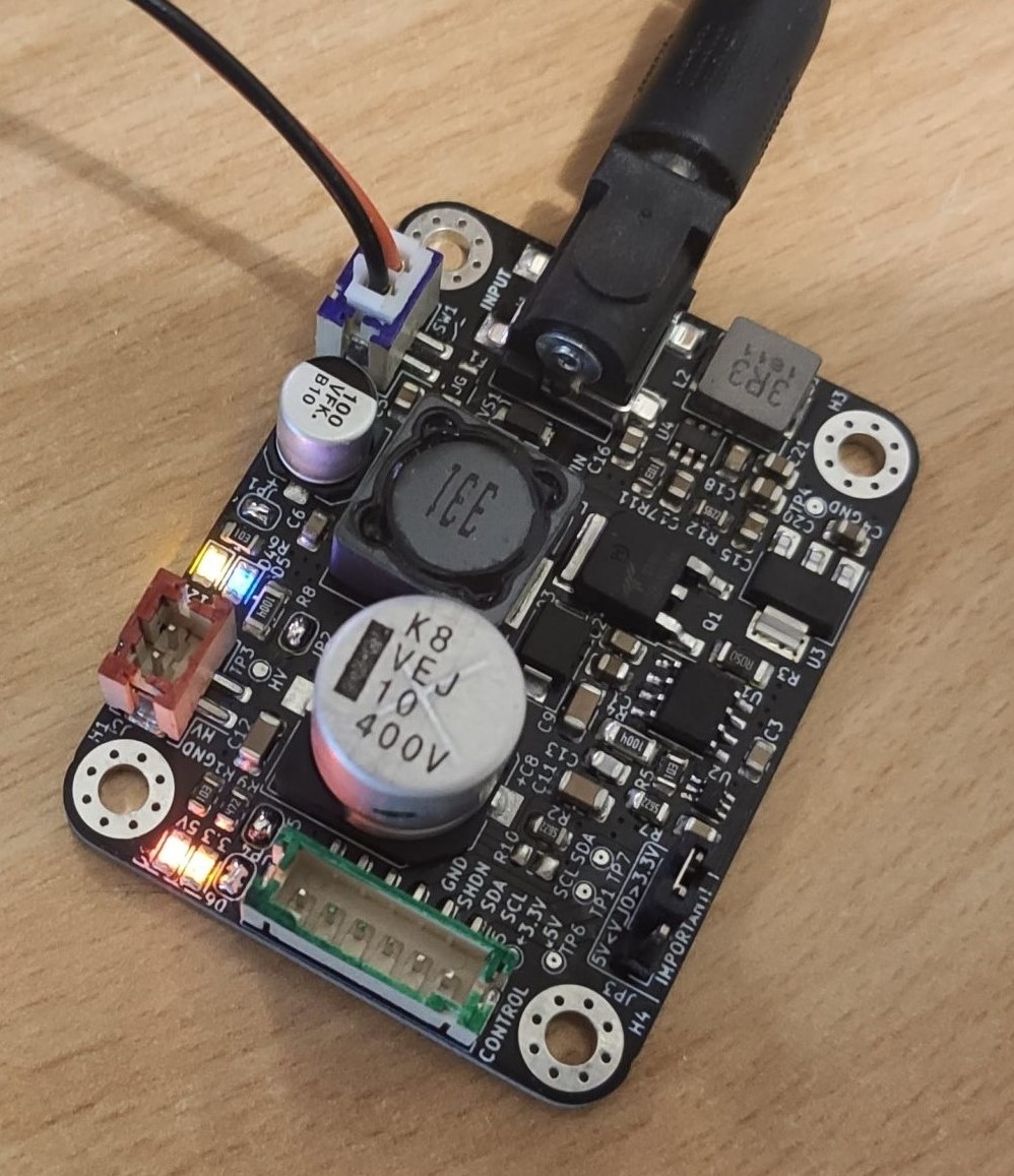
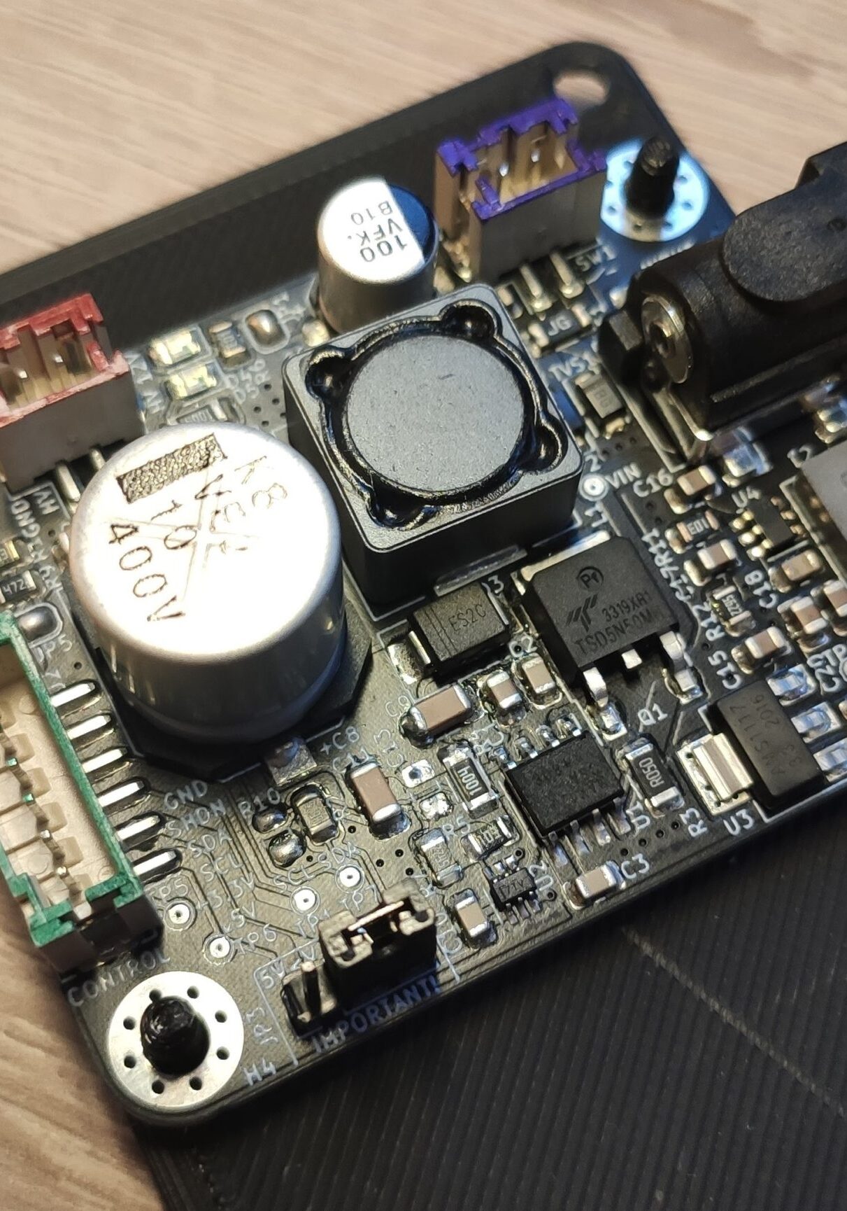
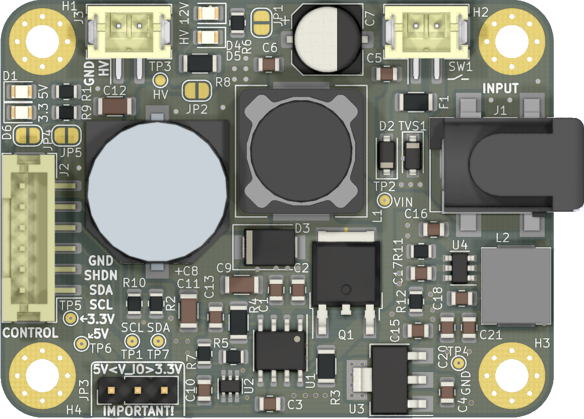
A detailed image of the top-side...
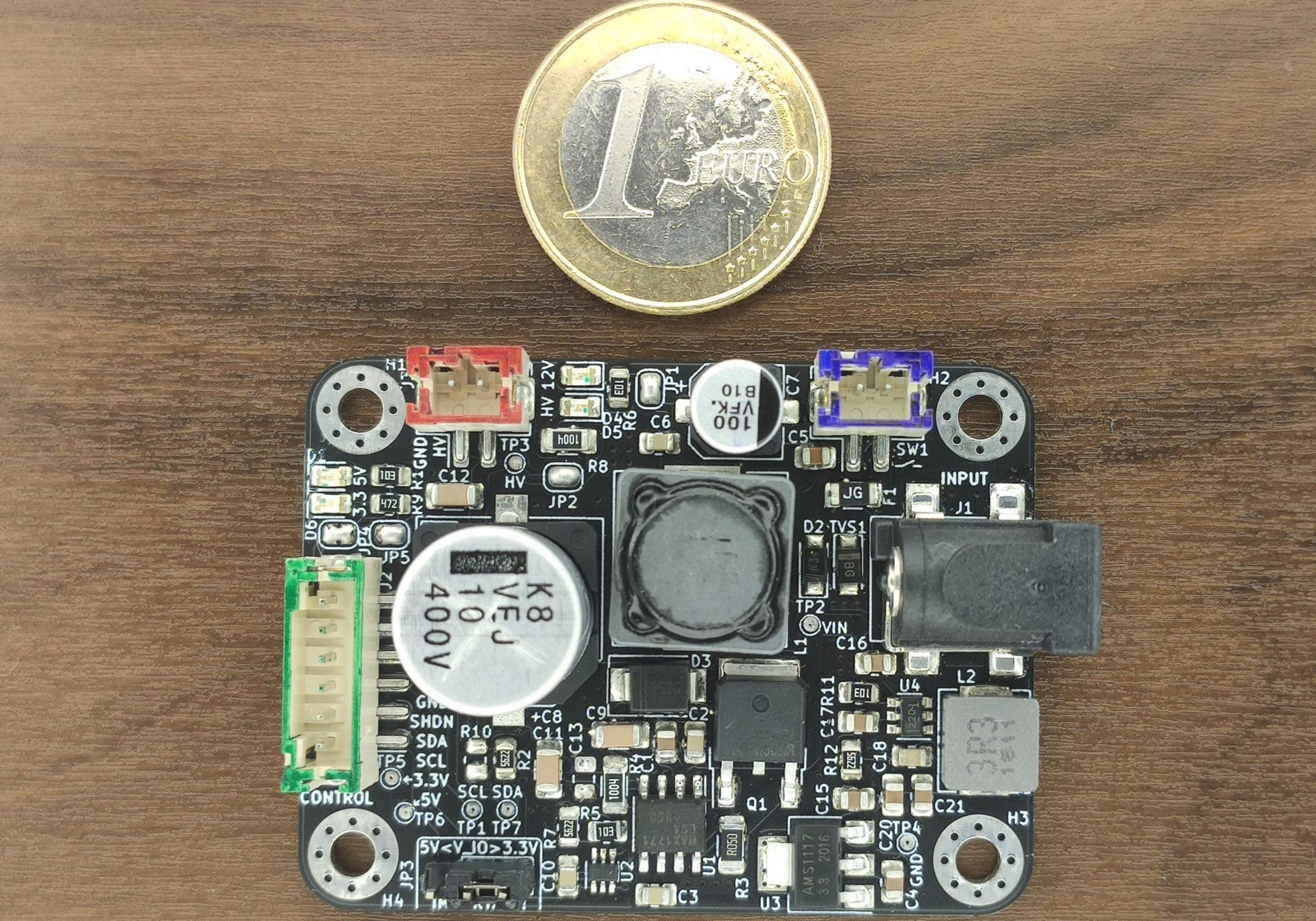
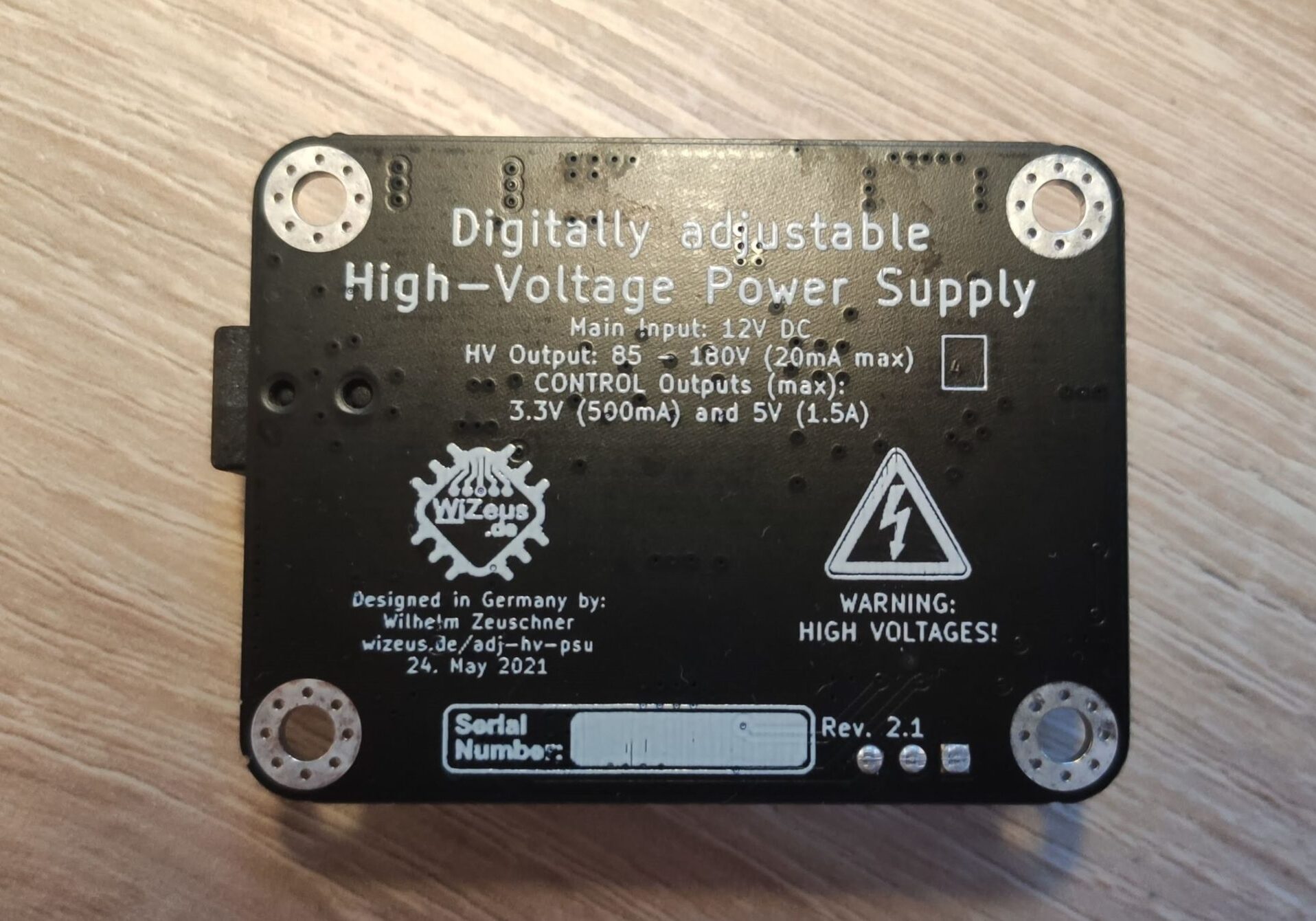
... and the bottom as well!
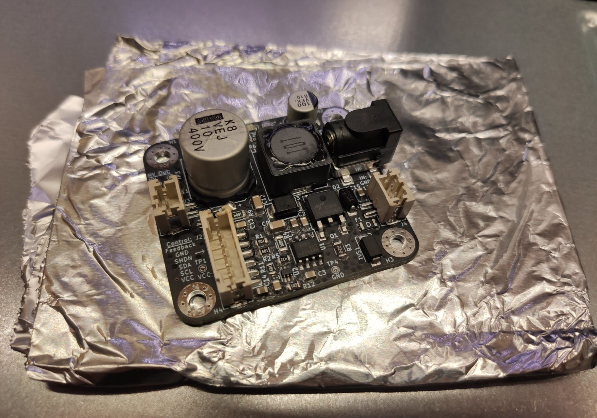
A finished module, right after reflow soldering.
(note that this image shows an earlier revision with slight differences to part placements, features etc.)
