Nixie Tube Clock
Table of Contents
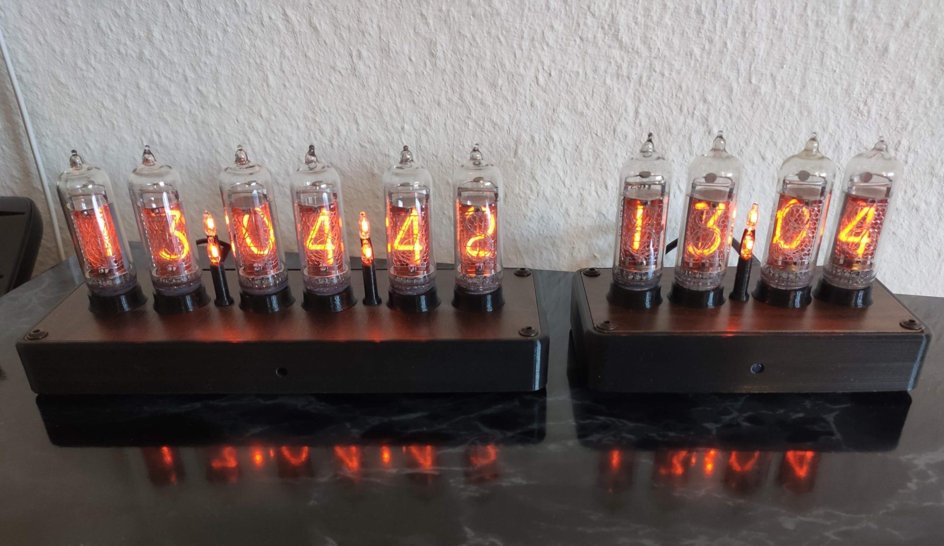
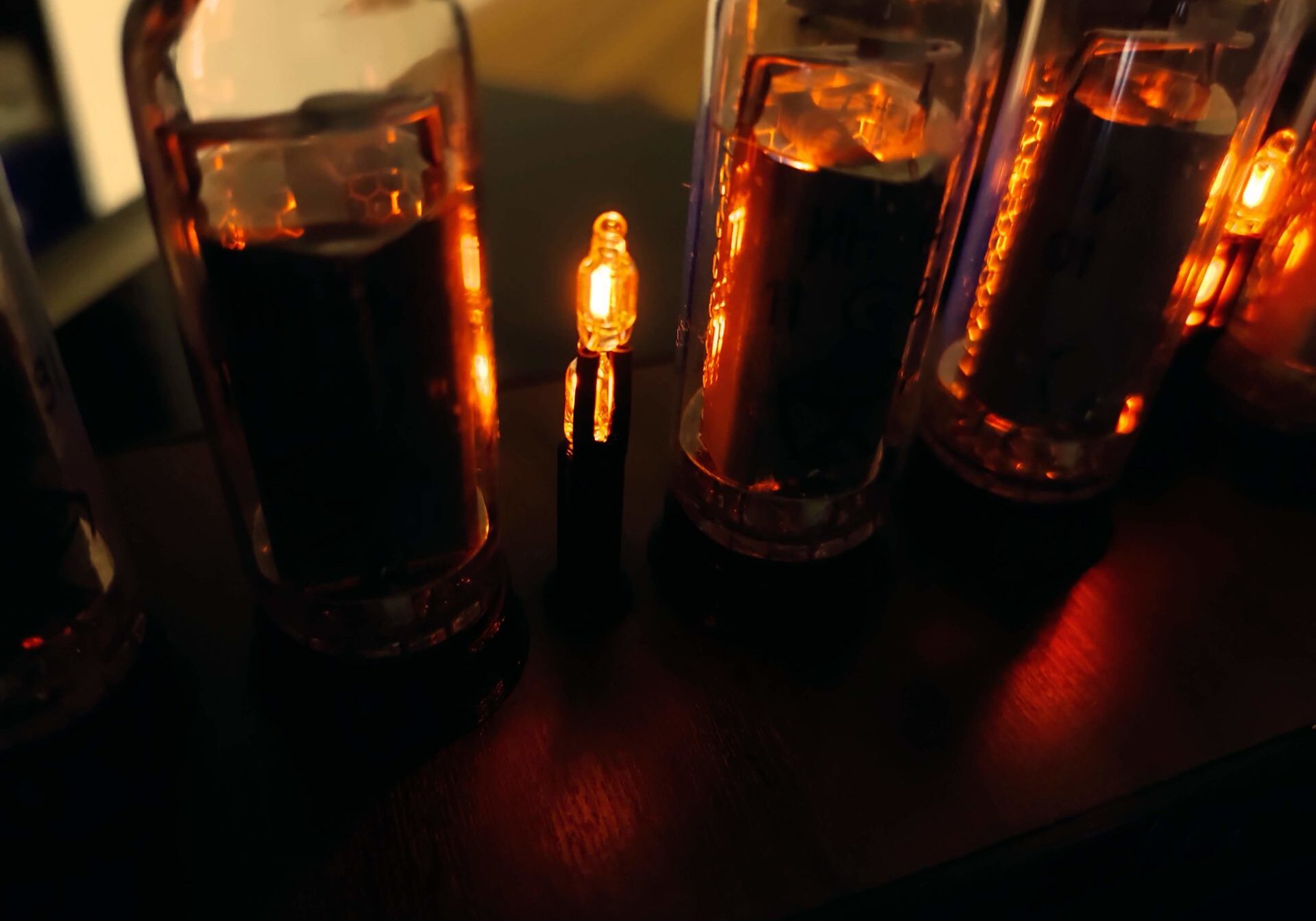
There's something about Nixie Tubes that just makes special and ideal for projects like clocks.
I'm certainly not the first hobbyist to make my own Nixie Clock but it's nevertheless the most important project to me since I enjoyed it a lot and learned so much.
I started to develop my own clock back in 2019. Previously I had no real experience in designing PCBs. This project really taught me a huge amount.
A spin-off of the original Nixie Clock Design, my digitally adjustable HV PSU module, is my first project that I have ever sold!
Overview
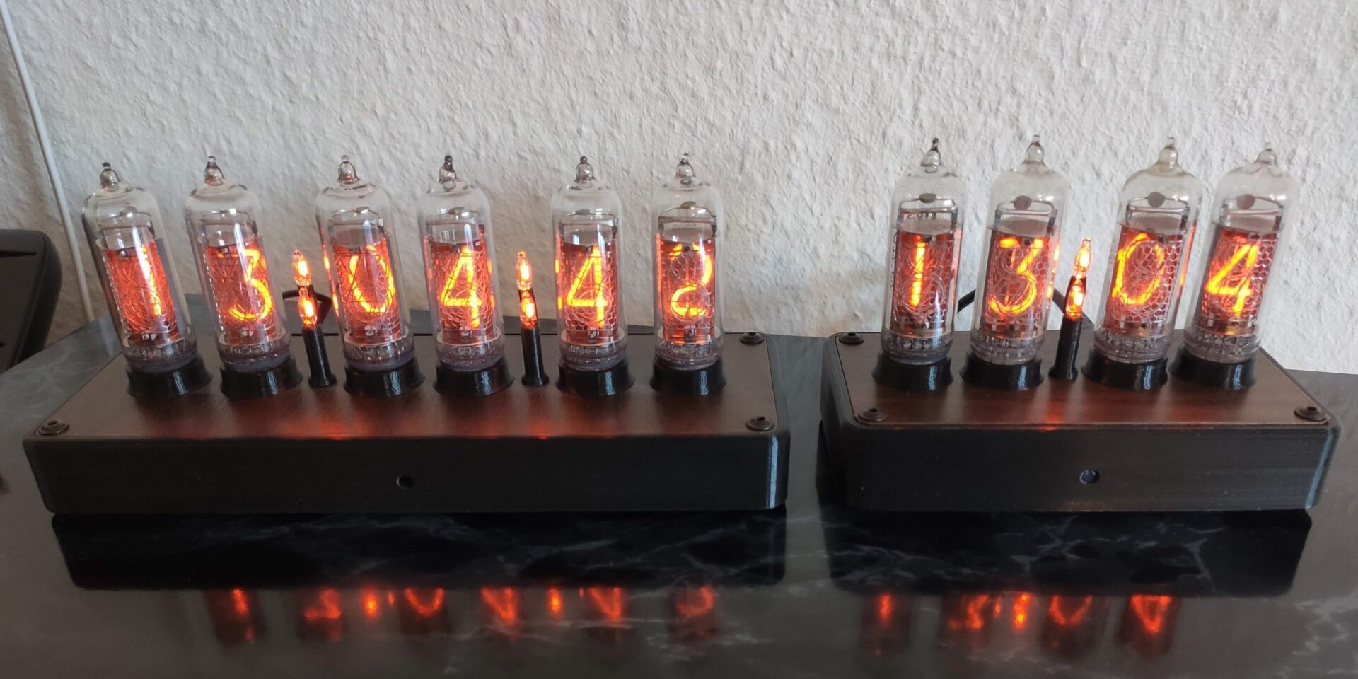
In 2019 I started to develop the first revision. Two other revisions followed and on top of that a version with just four Nixie Tubes.
Hardware
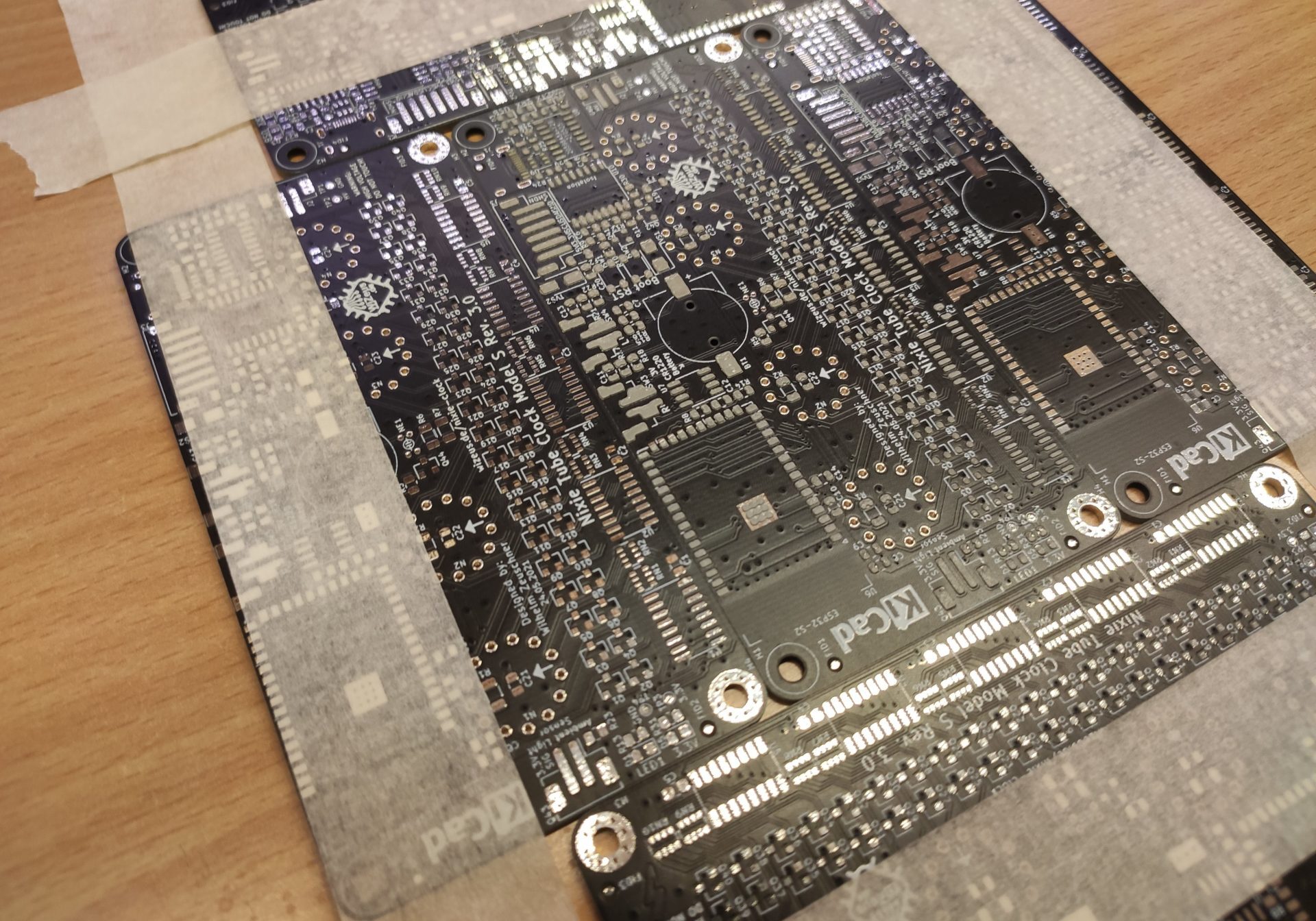
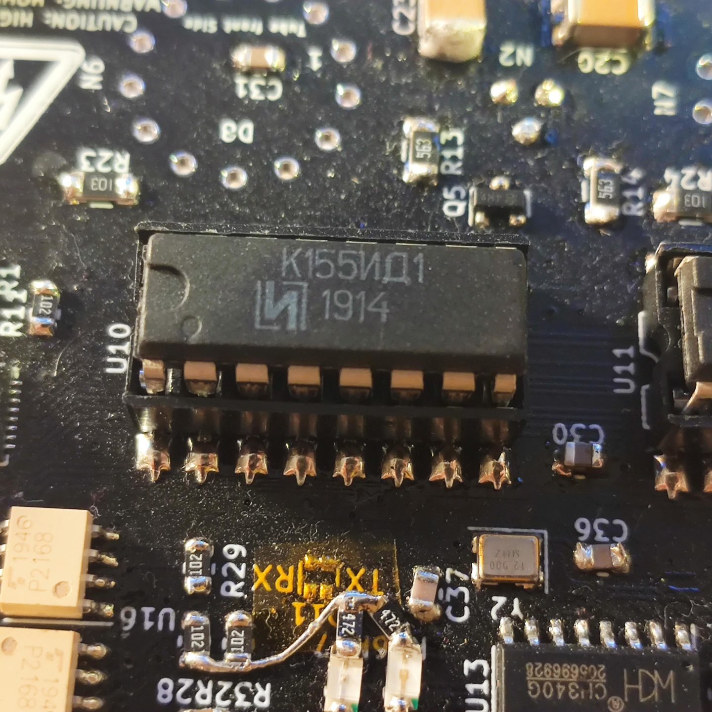
The PCB was designed in KiCAD. Over the few revisions many different approaches to controlling the individual numbers were taken. At first I used off the shelf Nixie Tube driver ICs (K155D1 or KM155ID1). These proved to be relatively expensive, somewhat hard to get and most importantly, very bulky.
To control all of the "parallel" driver chips with the limited IO pins I had available, I used an I²C port expander. The images below show the driver ICs and then port expander.
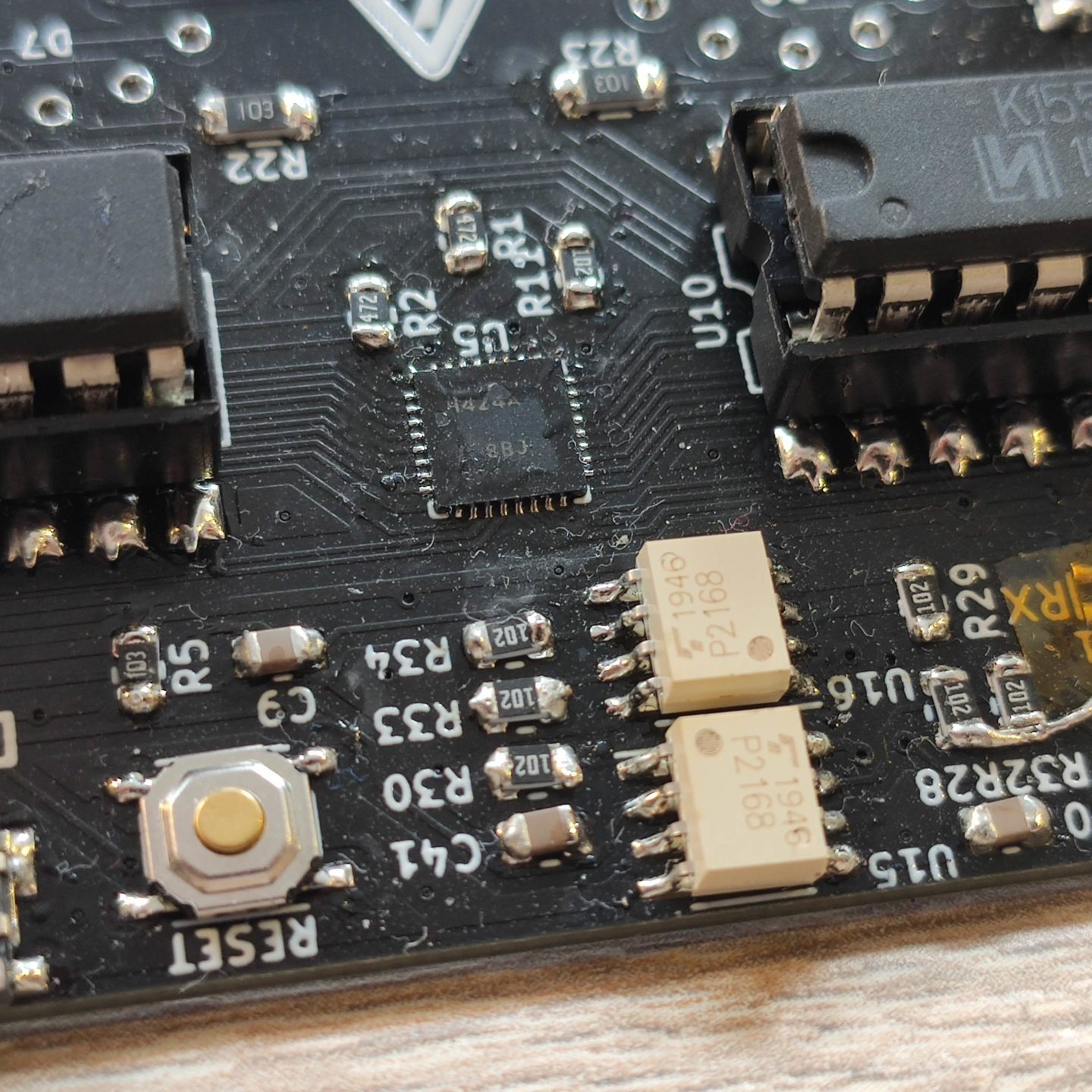
Initially I used an AtMega328PB microcontroller to control the clock. Later I switched to the ESP32-S2 since it was marginally cheaper and had significantly more features like Wi-Fi, more IO, more program space and a faster core.
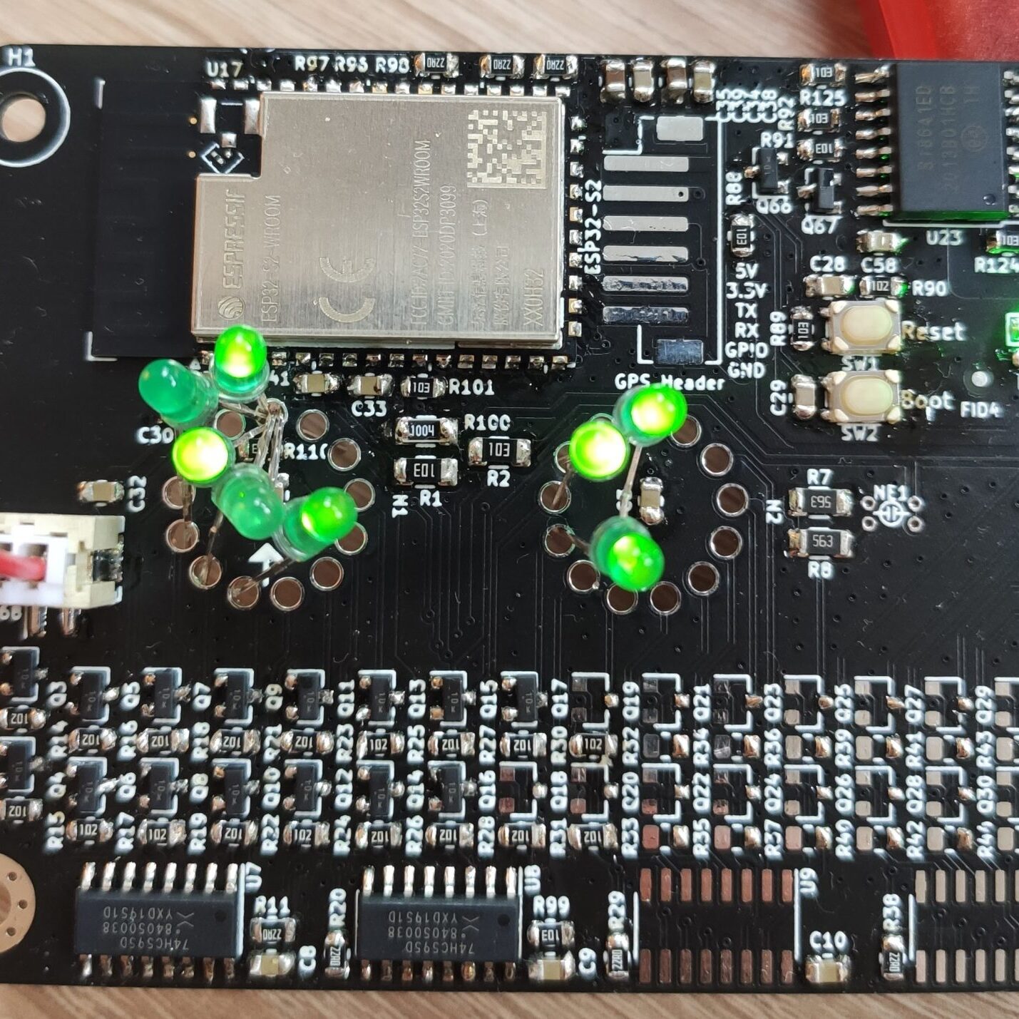
This photo shows how I tested my code for controlling the individual numbers: LEDs! They need no high voltage and are easy to insert into the holes for the tube's legs.
At this point I also decided to no longer use the conventional driver ICs to control the segments. Instead, I used shift registers with transistors for each individual number (bottom).
The PCB design grew more complex with each revision.
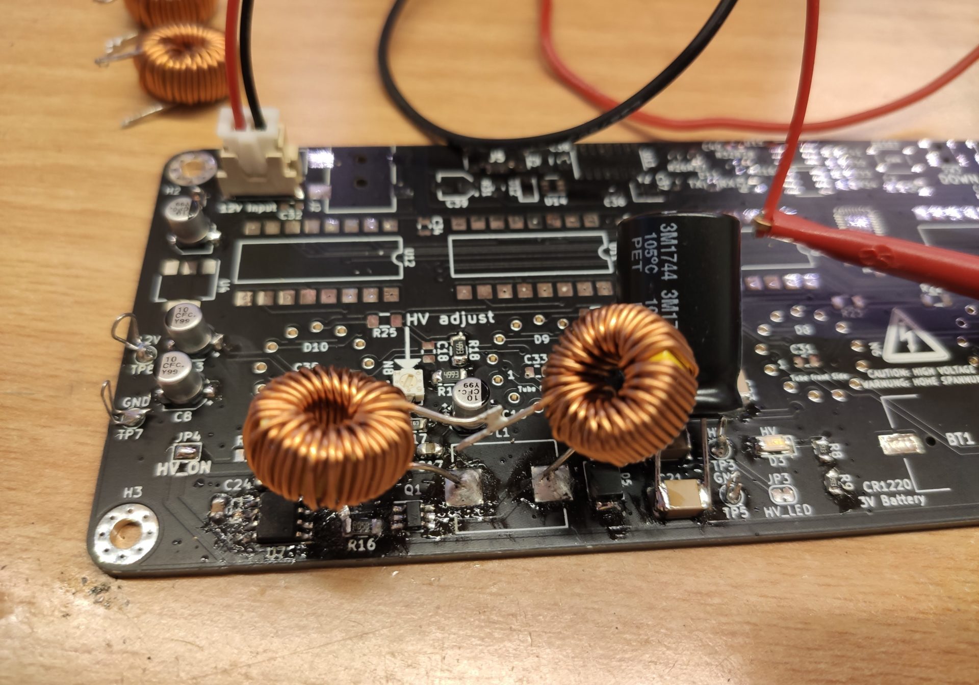
On the large 6-tube version of the clock, the high voltage boost converter is included on the PCB (bottom right). The output voltage of this converter can be digitally adjusted via I²C. This allows different brightness levels without the need to tweak a potentiometer. as far as I am aware, no other Nixie Tube Clock has this capability.
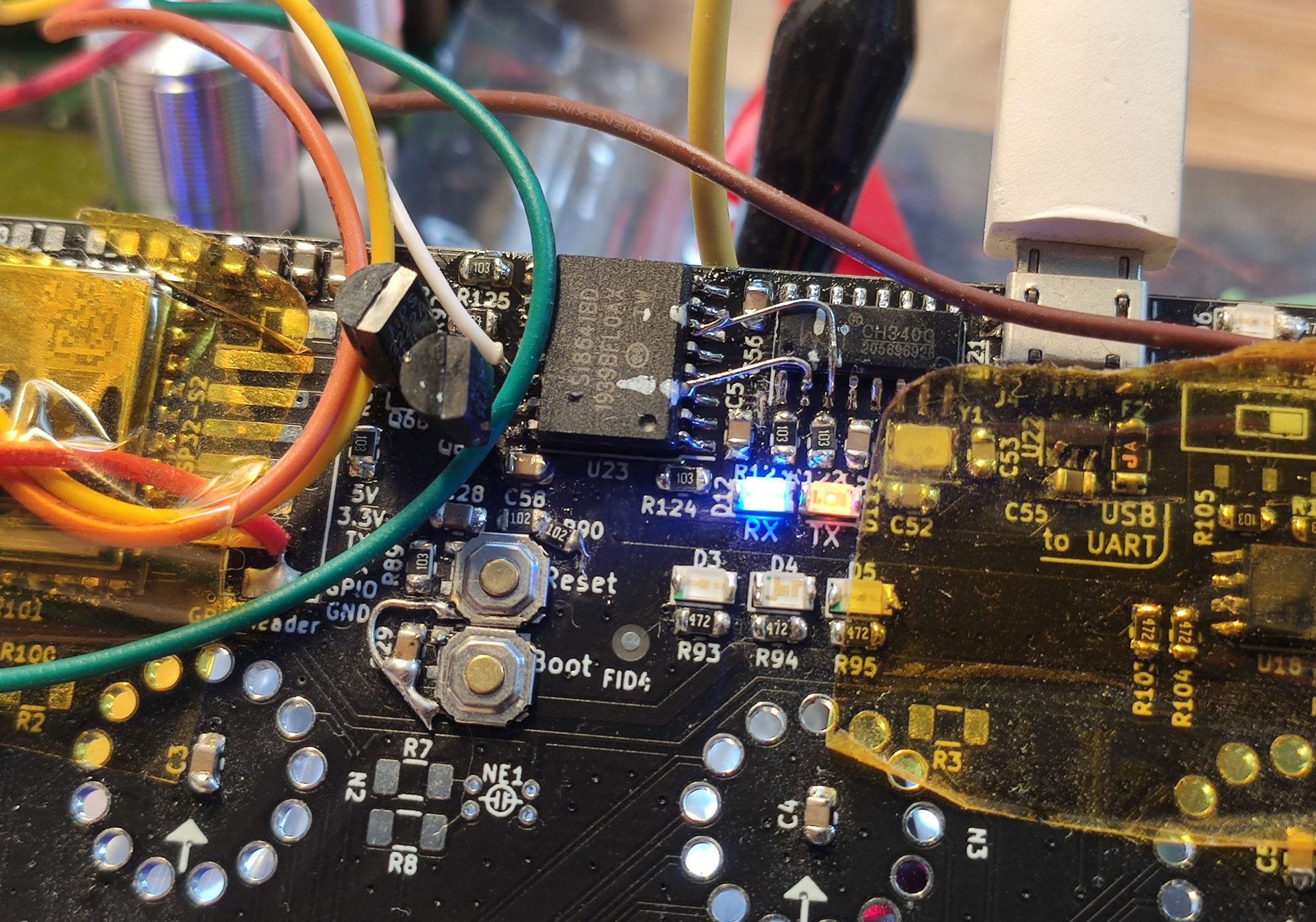
Another unique feature about my design is the galvanically isolated USB port (middle, where the white USB cable is). Via this port the microcontroller can be programmed and PC software can be used to control the clock's features. If anything should go wrong, for example of the high voltage rail gets shorted to the 3.3V rail, no damage occurs to the PC.
After the 6-Tube version was a proven design, I also made a smaller version with just 4 tubes. This one did not have enough available PCB space, so I spun off the HV PSU module into its own project.
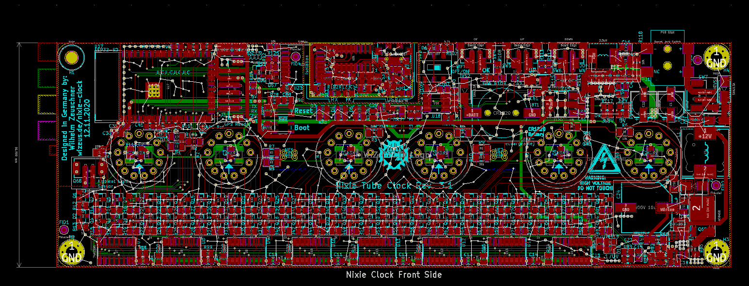
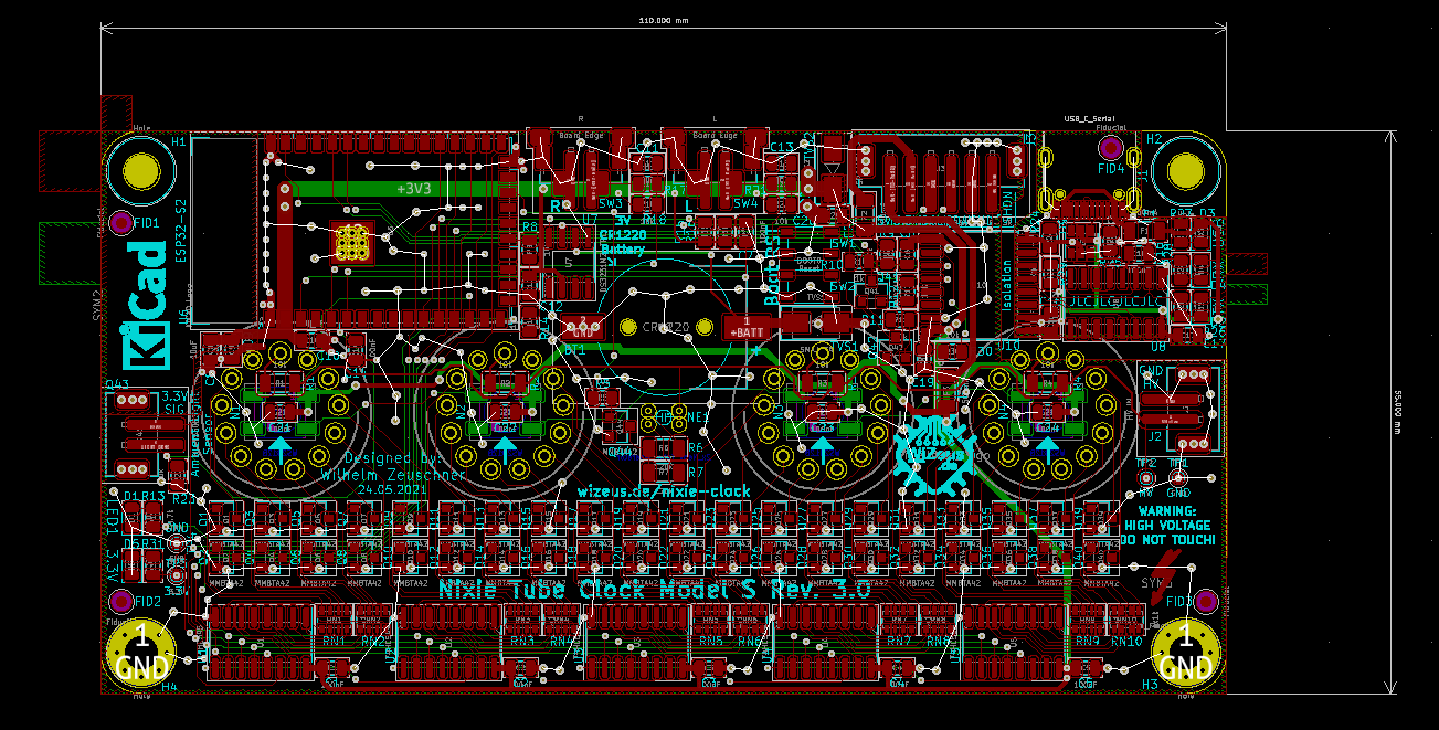
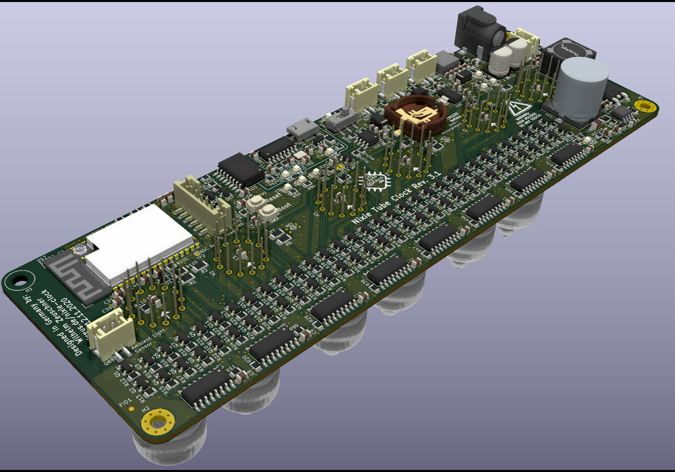
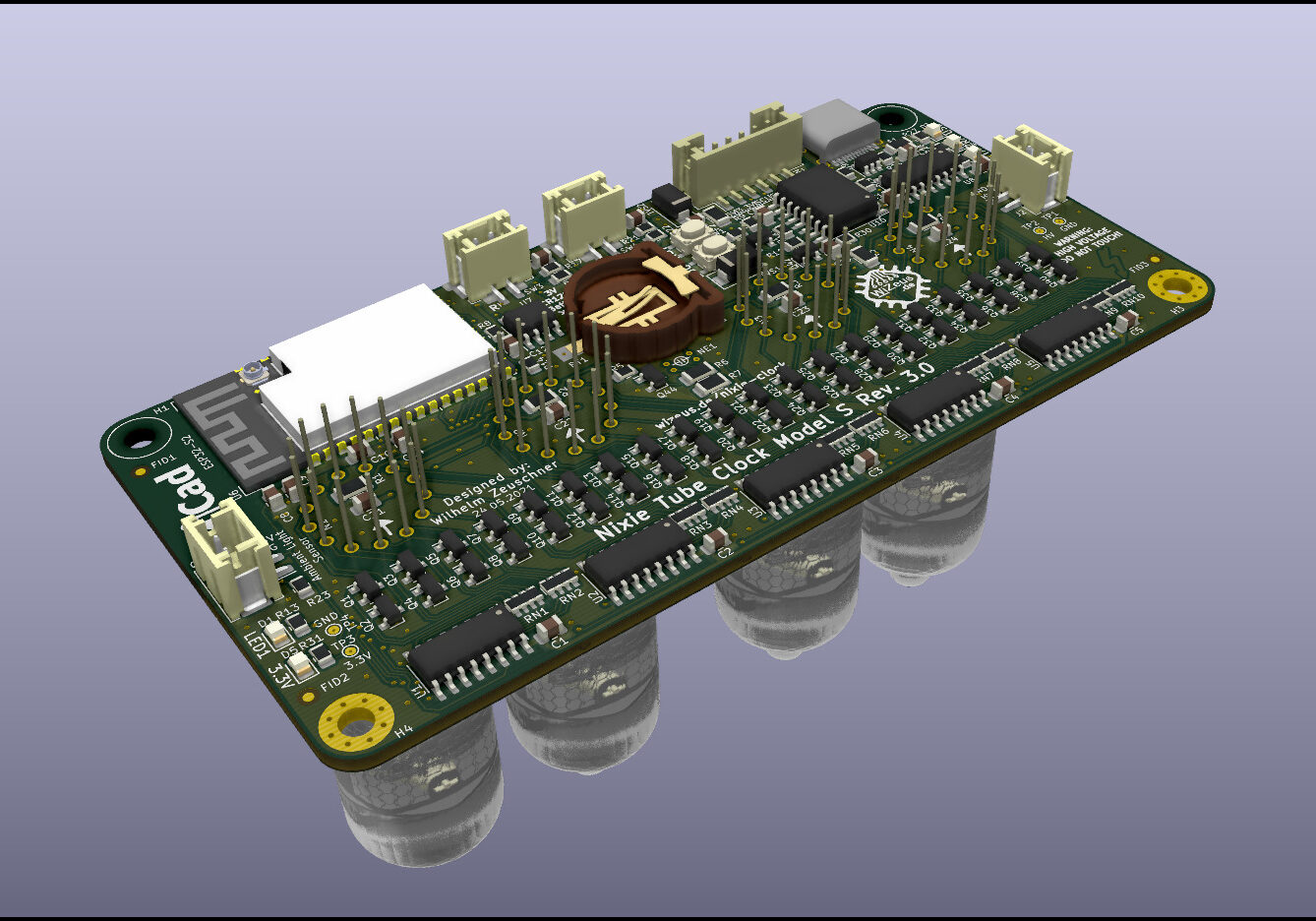
You can take a look at the 3D Model of the 6-Tube clock. Since it takes a long time to load, I have created a separate page for it.
Images
Here are some additional images of the project.
