Bachelor Thesis
Table of Contents
This page describes the work of my Bachelor Thesis (B. Eng. Electrical Engineering).
The objective of my work was to retrofit a modern airmass sensor into an old-timer BMW to replace an obsolete airflow sensor.
I received my Bachelor's degree in the Summer of 2022 from the University of Applied Sciences Emden / Leer.
This page aims to give a brief overview of my work. If you are interested in the full process, please have a look at the complete pdf document of my thesis.
Overview
The goal of this work is to enable the replacement of discontinued mechanical airflow meters with modern, actively produced electronic mass air flow sensors. These sensors are used in gasoline engines with fuel injection to achieve an optimal fuel-air mixture, ensuring the most efficient combustion possible.
In this project, a primarily mechanical airflow meter, which is connected to the engine control unit of a Bosch L-Jetronic system, is replaced. The system developed in this thesis was designed specifically for the BMW E24 635 CSi but can be generally adapted to various vehicles from around 1973 to 1981 from different manufacturers that use L-Jetronic systems.
To achieve this goal, a flexible microcontroller-based control system with custom hardware and software was developed.

Hardware
Introduction
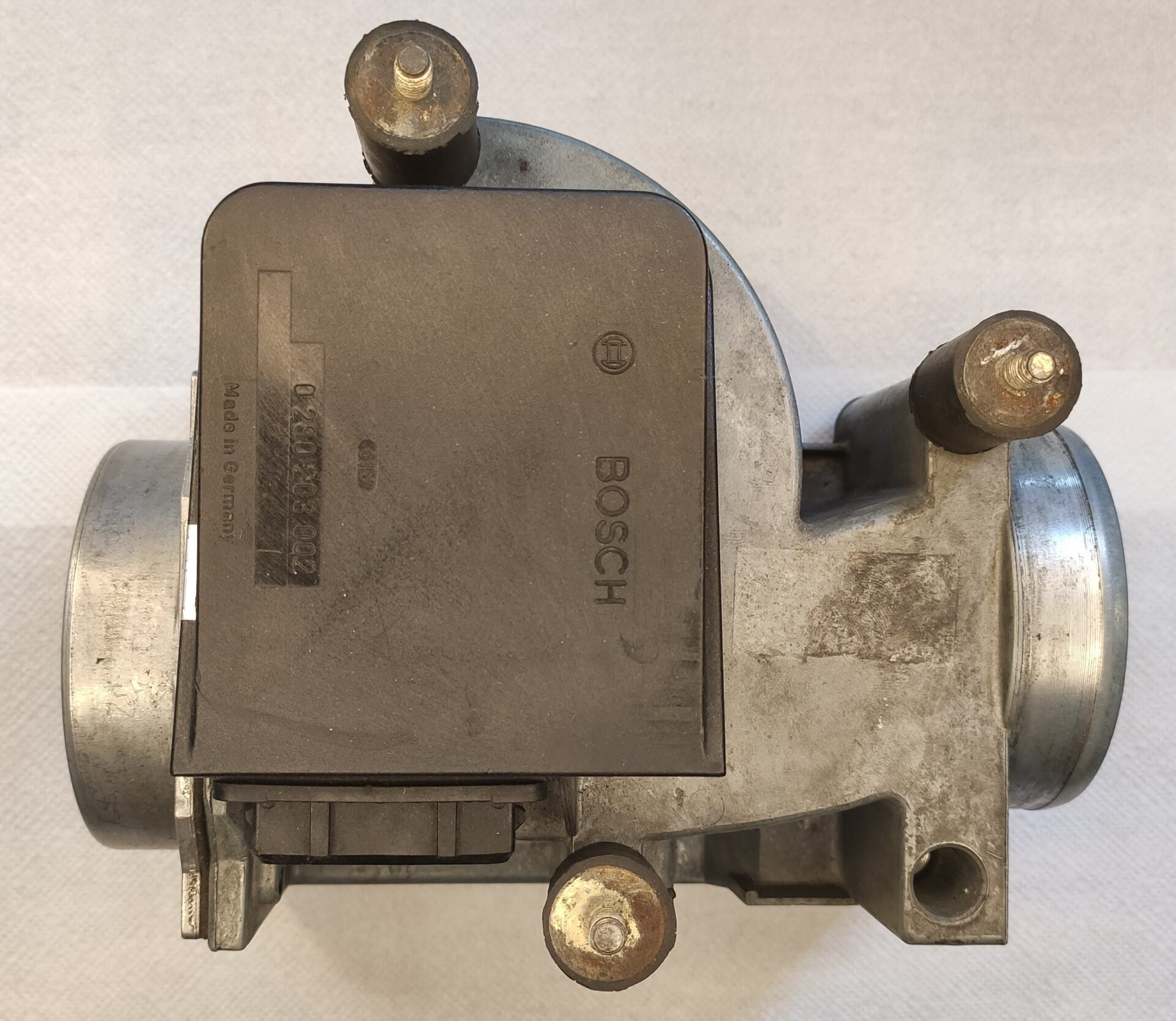
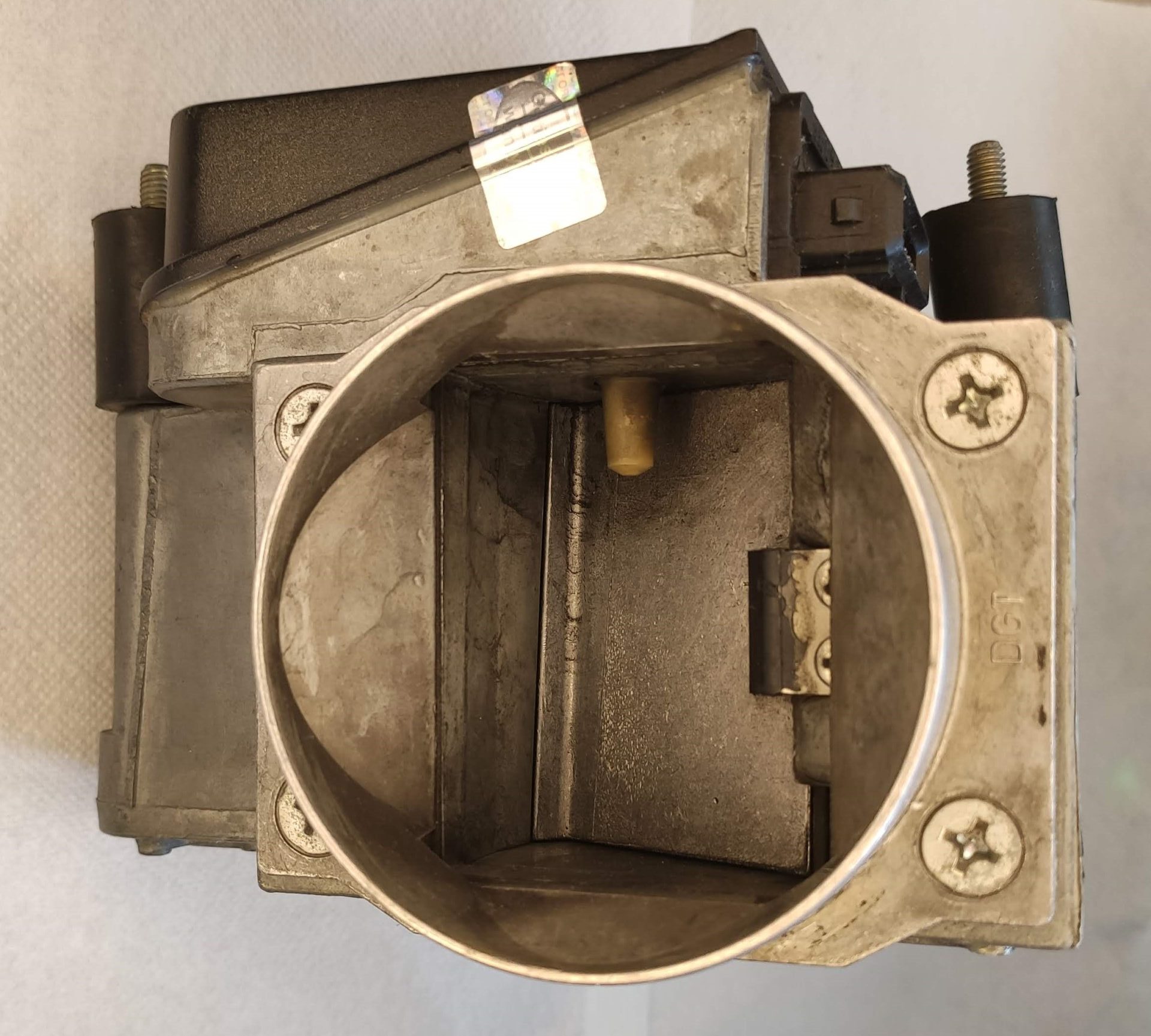
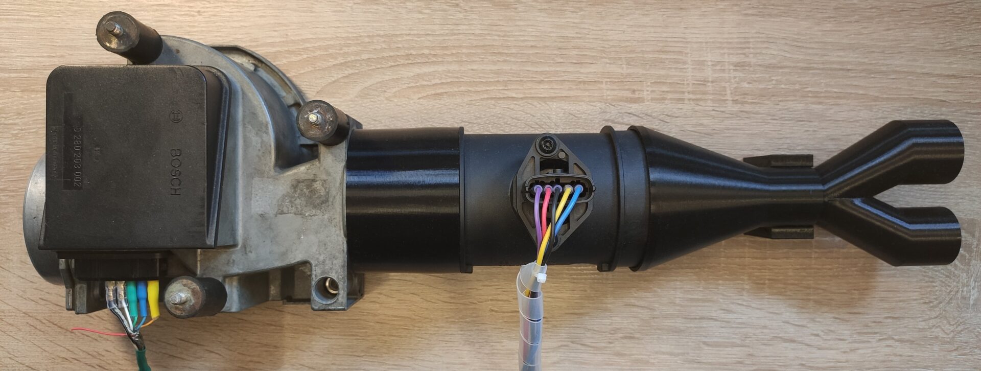
High performance cars of the era, like the BMW E24 635CSi, used fuel injection into the air intake of the engine. In order to control the amount of fuel to be injected, an ECU measured the air flow into the engine. The airflow was measured with an electro-mechanical airflow sensor, which is shown below (Bosch part number: 0280203002).
These devices essentially have a potentiometer attached to a rotating shaft connected to a flap inside the tube which is moved by the air that is pulled into the engine.
The potentiometer of the airflow sensor is connected to an ECU (shown below). The ECU then controls the amount of fuel that is injected into the air intake of the intake. Note, that this generation of gasoline (petrol) engines did not have direct fuel into the actual cylinders injection yet.
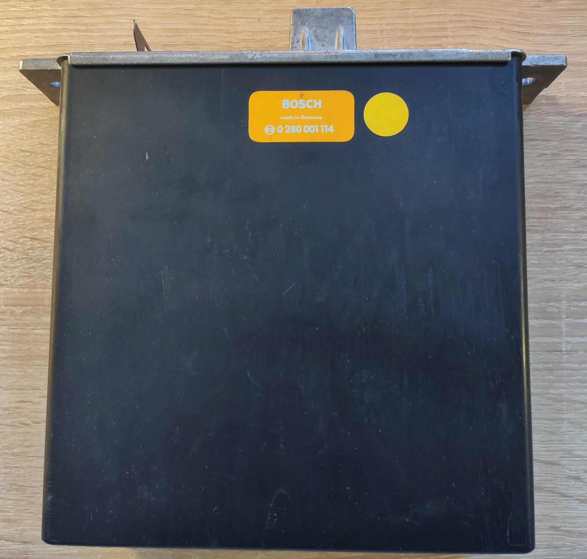
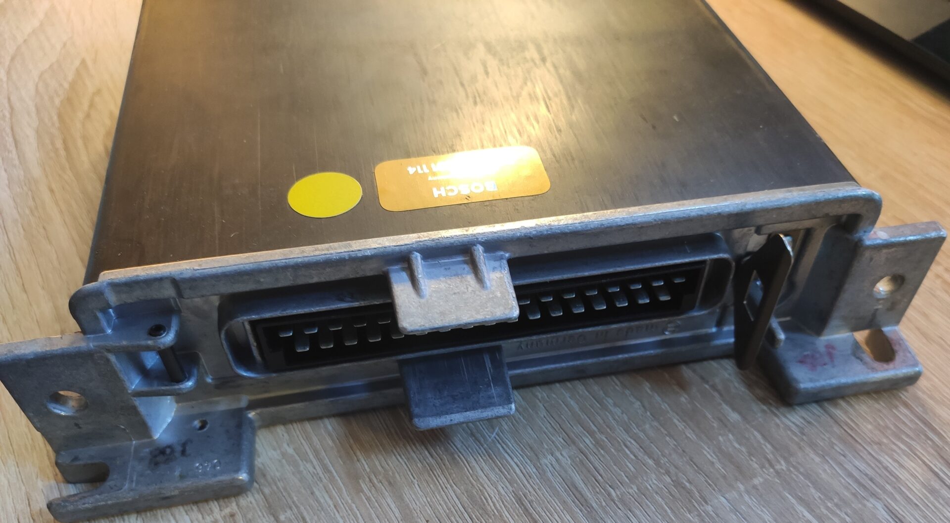
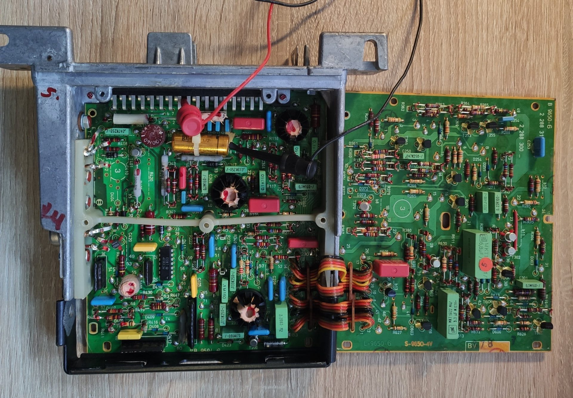
By modern standards, both the ECU and airflow sensor use dated technology. Since a potentiometer was used inside the airflow sensor, it would eventually fail due to mechanical wear. Replacing it with an original part of the era is quite costly. Thus a modern replacement makes sense which doesn't have the same supply issues.
I developed such a replacement. It uses a modern air mass sensor (Bosch part number: HFM 5) which can be used instead of the old part.
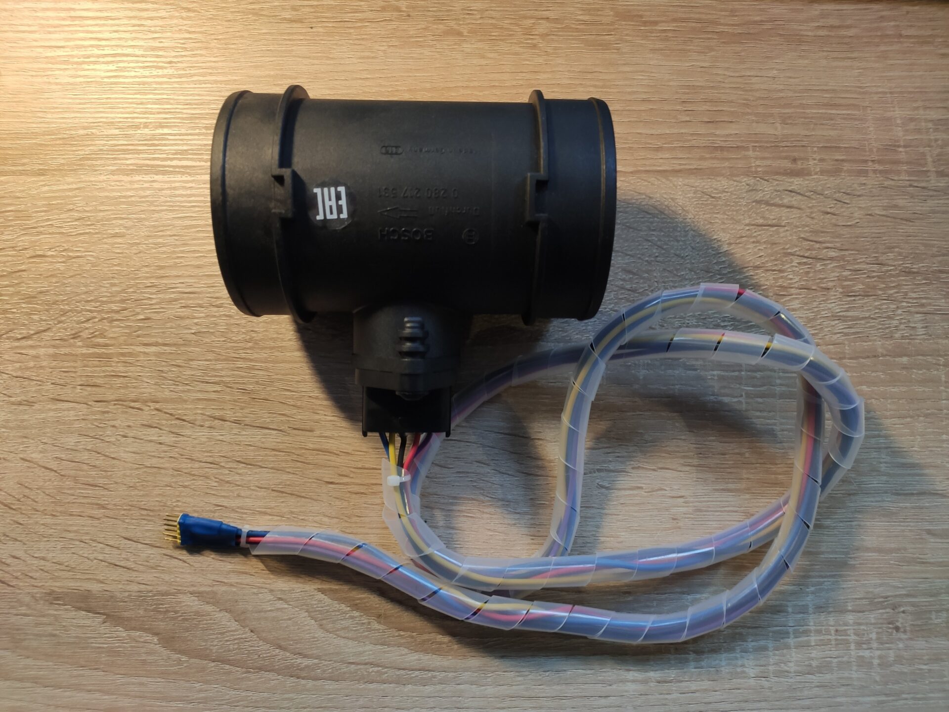
Measurements
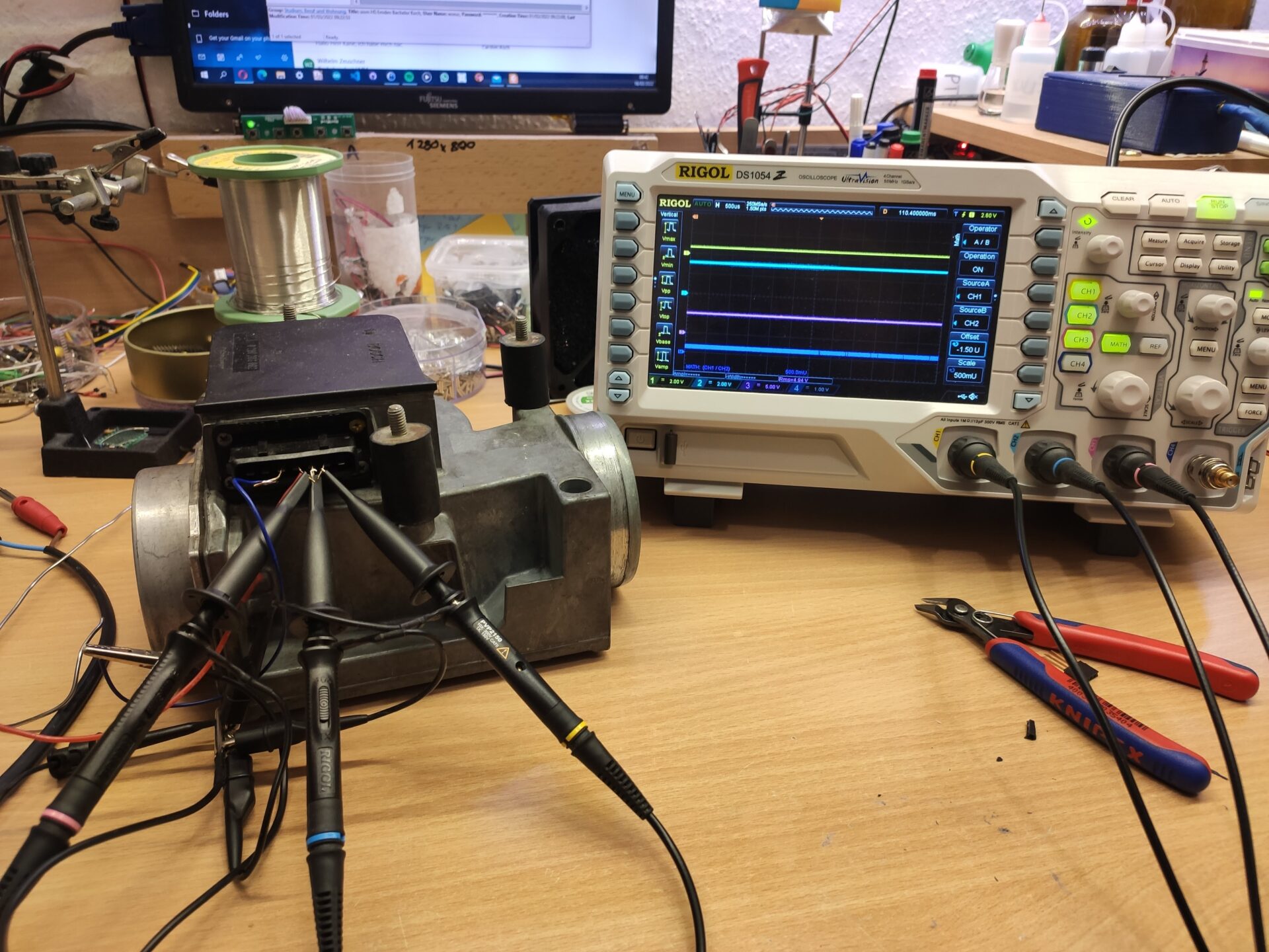
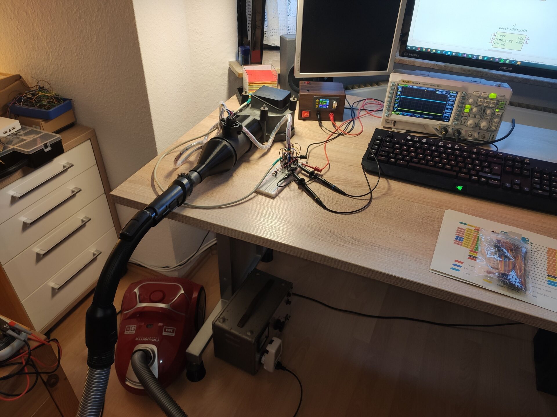
During the development process I needed to verify the output signals of both sensors under the same conditions. In order to be able to test it in the confines of my own home, I designed 3D printed parts to be able to suck air through both sensors with a vacuum cleaner. This contraption is shown below. The results were sufficient to create a mapping between both sensors' output signals.
Data processing
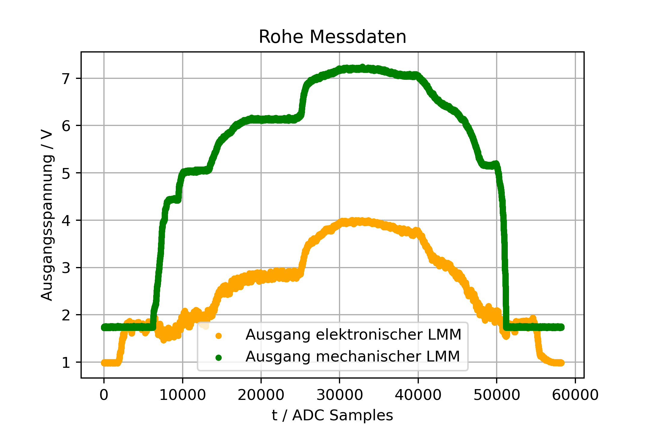
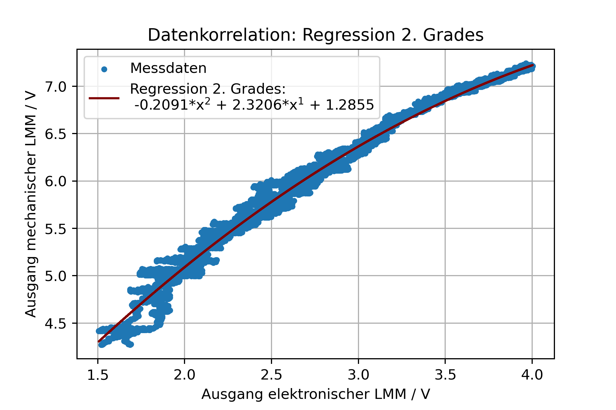
Based on the values I measured, I was able to generate a mathematical equation to translate the output of the modern sensor to what the old sensor would output at the same airflow level. This was later used in the firmware to determine the correct output signal.
Both the old air flow sensor and the modern replacement have a thermistor built in. Just like with the air flow data, I collected measurements and created a mathematical function to calculate the correct output function based on the data.
For processing the data, I used a Jupyter notebook script I wrote. It's available on GitHub.

PCB development
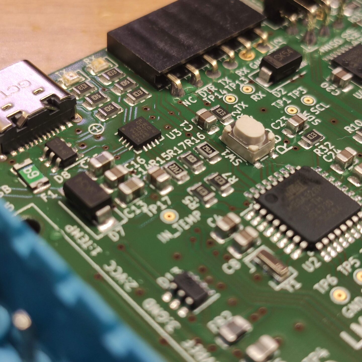
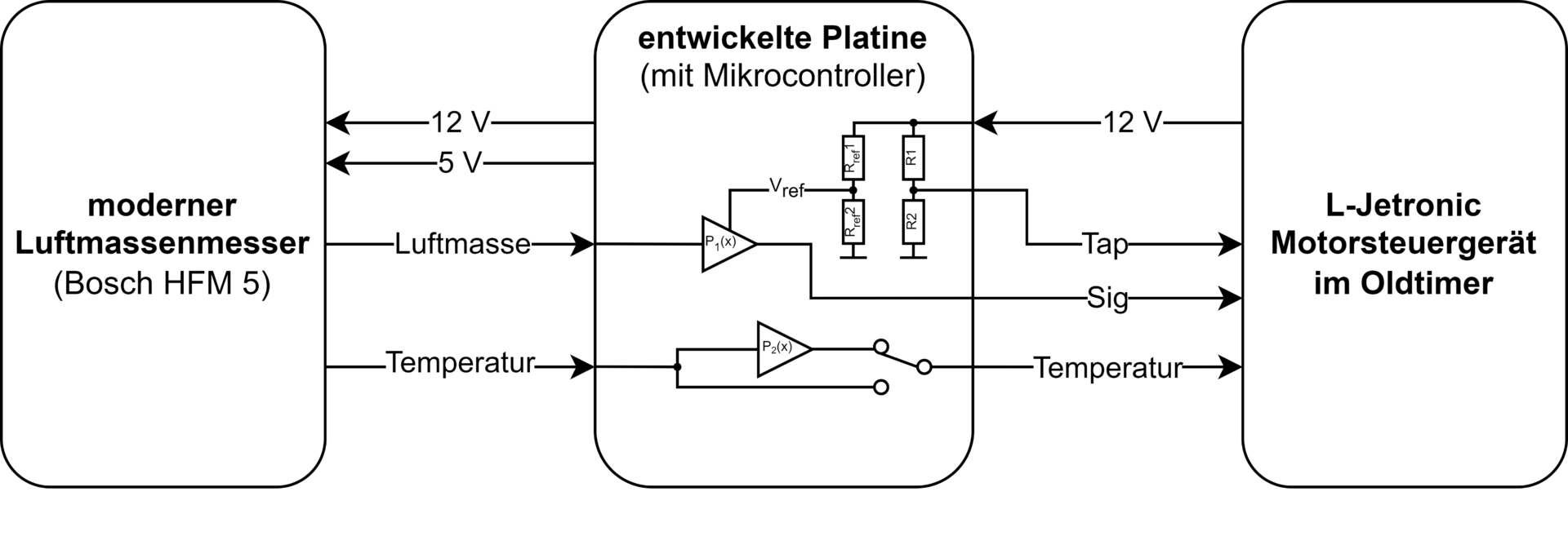
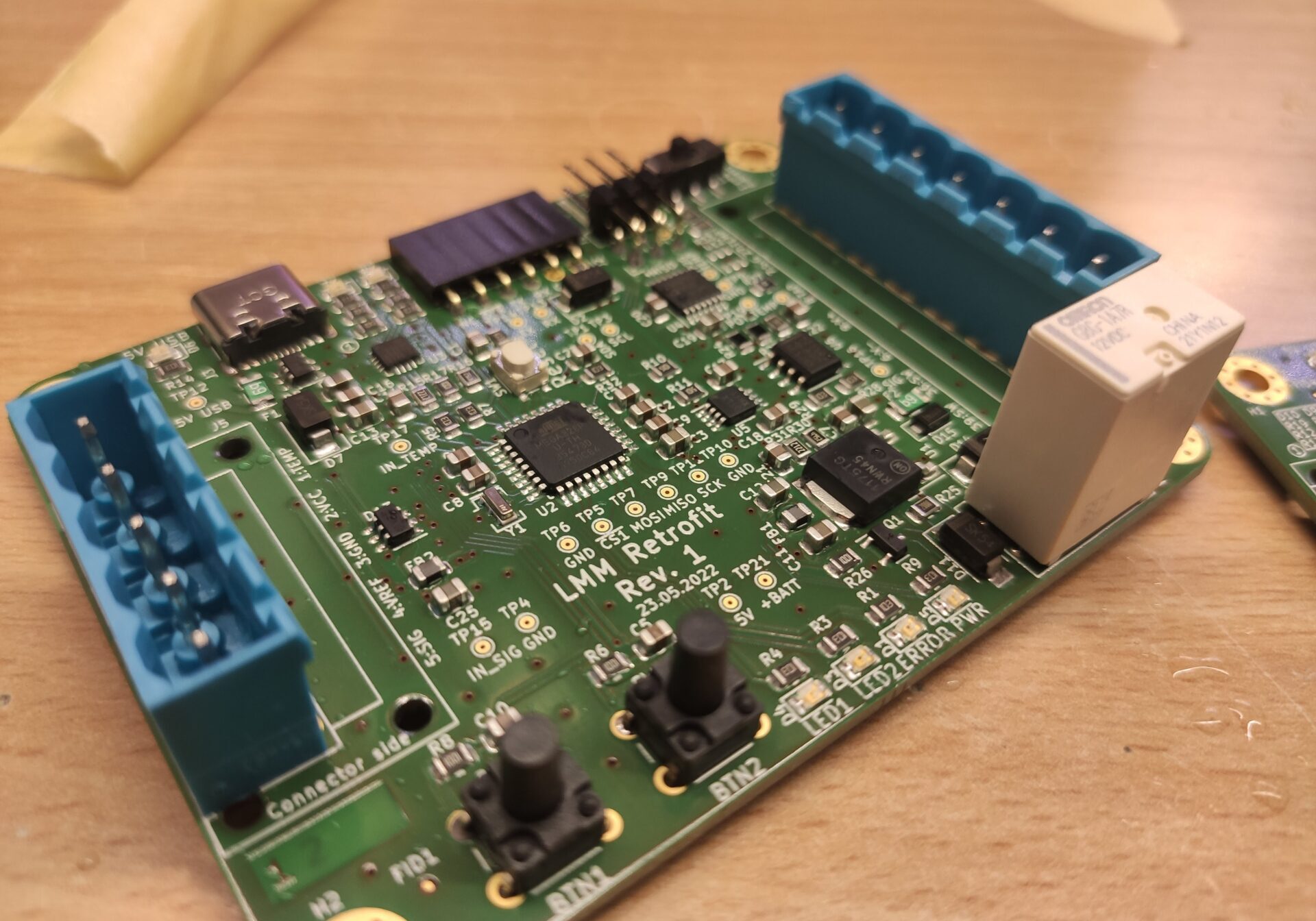
Next, I developed a custom PCB to emulate the necessary signals. The MCU samples the analog data of the modern airmass flow sensor (left connector) and outputs the corresponding signals on the right connector, which is connected to the ECU.
I decided to use the Atmel ATmega168 microcontroller due to my extensive experience with this particular IC.
Notable parts of the circuit include the analog signal processing.
The analog output signal that goes to the ECU is generated using a DAC. Special care needed to be taken to emulate the air flow sensor properly. The circuitry inside the old air flow sensor is not just a simple potentiometer. It also had a "tap" signal. Likely this serves as some sort of scaling value for the ECU's signal processing.
Additionally the proportionality with regard to the 12 V supply voltage had to be maintained. Using a regulated voltage as the DAC's reference was not possible since the car's 12 V bus voltage can vary significantly.
Since the potentiometer is just a divider, it's output would change proportionally with the supply voltage.
Thus, the DAC's reference voltage was based on the 12 V input voltage by using a resistive divider as well.
The NTC of the modern air mass flow sensor can either be directly connected to the ECU or emulated by an on board digital potentiometer.
The basic operation of the PCB inside the vehicle is shown in the block diagram below.
The PCB design files are available on GitHub. I had to remove some of the 3D models since I don't own the rights to publish them.


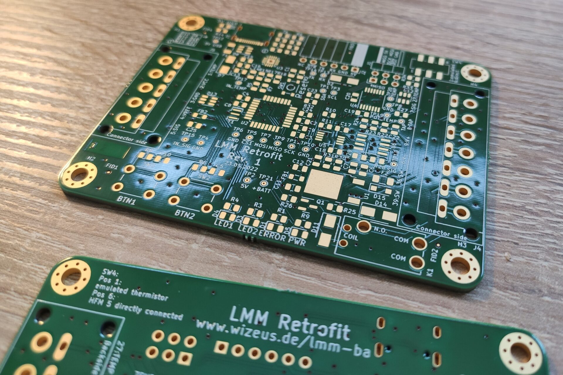
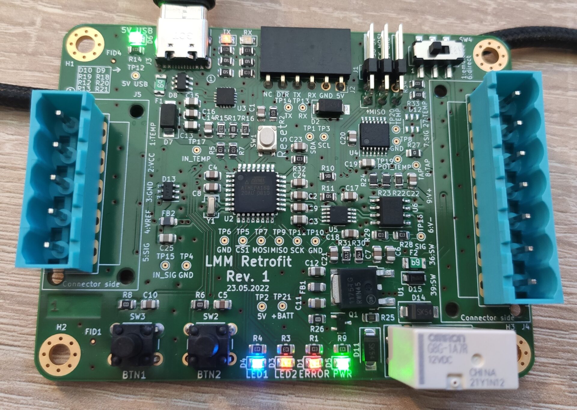
I did all of the assembly and bring up of the PCB myself and it turned out to be a really beautiful board.
Firmware
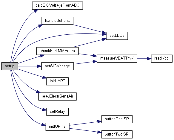
I have published the firmware that runs on the microcontroller and the Jupyter Notebook script for the data processing on GitHub.

Mechanical
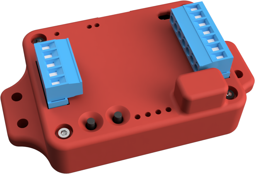
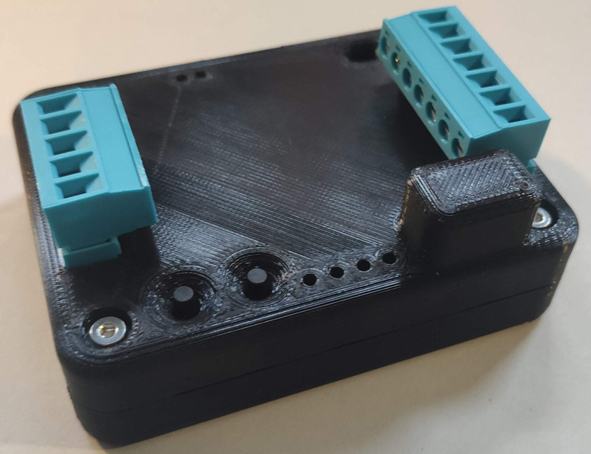
I designed a basic 3D printed case in Fusion 360 for the PCB. The STEP-model is available on GitHub.
Verification and outlook
Unfortunately the design never ended up in a real vehicle, mostly due to time constraints.
However, lab measurements were done to verify the performance. The oscilloscope capture below shows the output signal of the developed PCB (yellow) vs the output signal of the mechanical air flow sensor (pink). Both sensors were in series and a vacuum cleaner was used to suck air through both sensors.
It is clearly evident that the replication closely resembles the signal of the mechanical airflow meter. It can be observed that the signal output by the LMM retrofit exhibits some noise. Measurements show that the signal from the modern airflow meter has significant noise. This signal is sampled by the PCB, and a corresponding output is determined based on this data. The signal is filtered by a low-pass filter, implemented in hardware, before sampling. If the time constant were further increased, the step response would no longer be satisfactory. Therefore, a compromise was made in the current implementation to balance an adequate step response with acceptable noise levels.
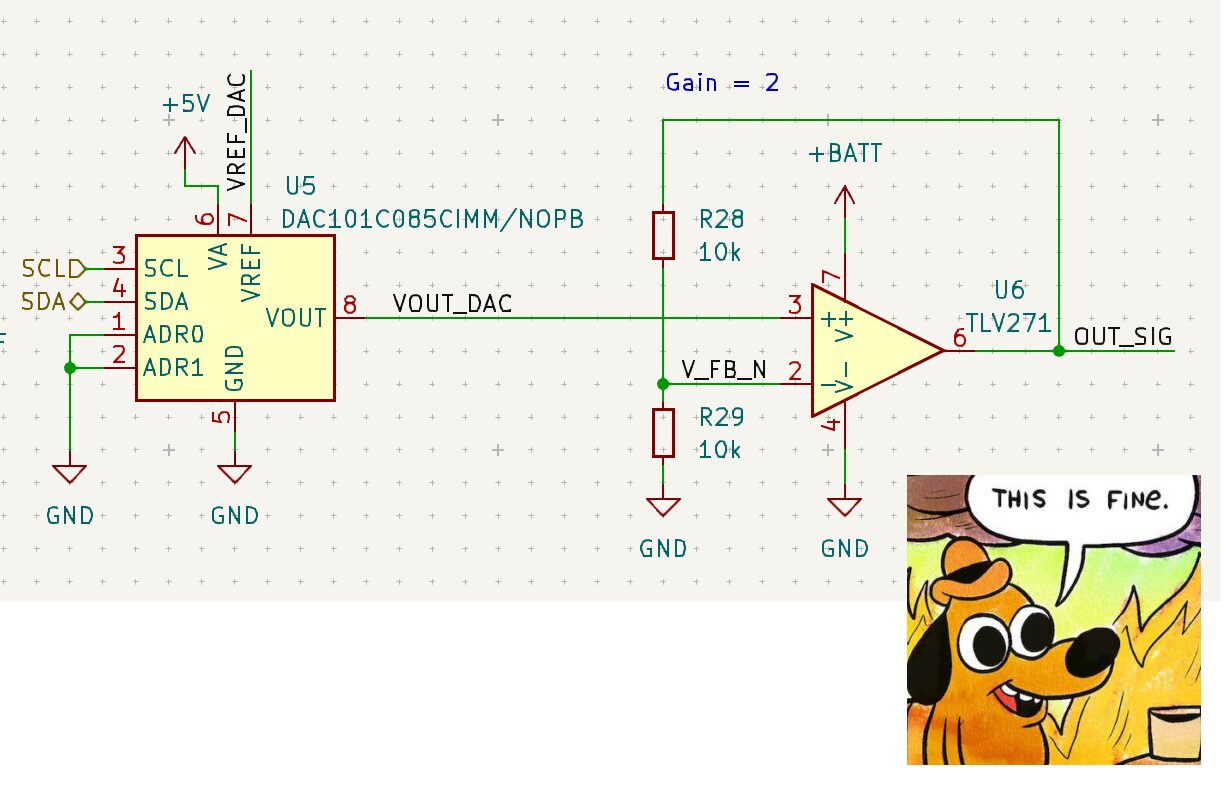
Looking back at the project, I am very proud of my work. There are some small design decisions I would make differently now, that I am more experienced. Especially regarding the output signal of the op-amp that generated the output signal for the ECU. It is not protected against any kind of electrical fault at all...

Thanks!
I want to expressly thank my professor Prof. Dr. Carsten Koch who supervised my thesis. In my eyes he is an amazing educator and I am grateful to have visited his lectures and that he supervised my thesis.
Also I would like to thank Ewald Zimmermann for being the second examiner of my thesis.
Full thesis document
My full bachelor thesis pdf document is available for download.
Bachelorarbeit-Hans-Wilhelm-Zeuschner-LMM_Retrofit.pdf
It is published under Copyright Wilhelm Zeuschner 2022 all rights reserved.
Images
Here are some additional images of the project.

Further reading
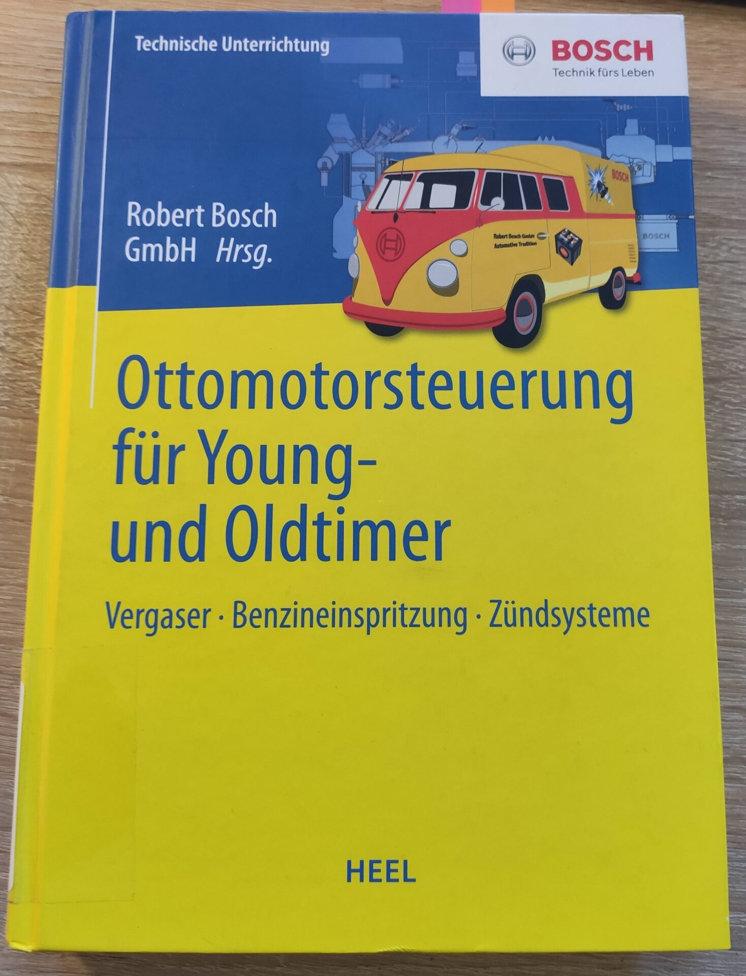
If you are interested in more details about the history of fuel injection and other topics in automotive engines and you know German, I recommend to read the following book:
BOSCH: Ottomotorsteuerung für Young- und Oldtimer
ISBN: 978-3-95843-331-1
This book served as a valuable source of information for my thesis. The book is written in German.
